Air outlet panel assembly and vertical air conditioner
A vertical air conditioner and air outlet panel technology, which is applied to air conditioning systems, heating methods, airflow control components, etc., and can solve problems such as no driving scheme
- Summary
- Abstract
- Description
- Claims
- Application Information
AI Technical Summary
Problems solved by technology
Method used
Image
Examples
Embodiment 1
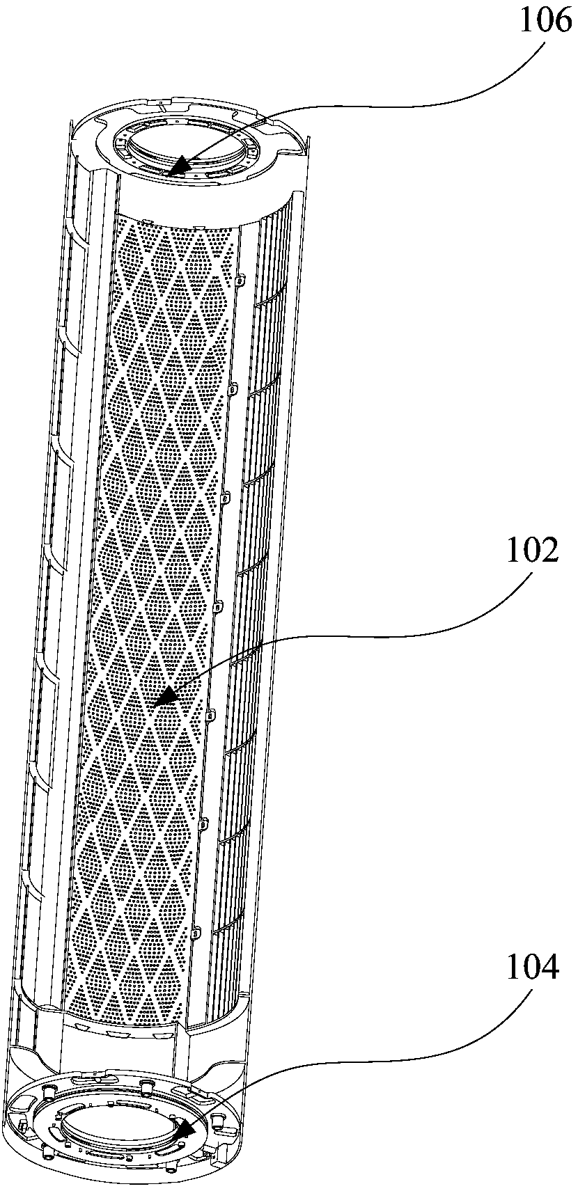
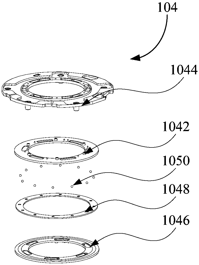
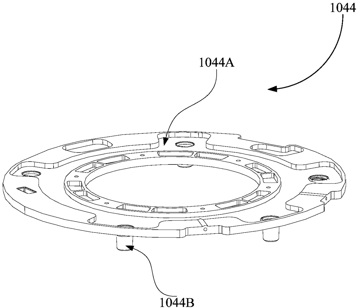
[0083] Such as Figure 2 to Figure 5 as well as Figure 10 As shown, when the rotating mechanism 104 includes the first rolling bearing 1042, in the above embodiment, preferably, the arc-shaped air outlet panel further includes: a first fan-shaped plate 1026, which is horizontally arranged on the inner side of the bottom of the arc-shaped air outlet panel, fan-shaped The bottom plate is provided with a first group of connection holes; the second fan-shaped plate 1036 is arranged on the top of the first fan-shaped plate 1026, and is arranged in parallel with the first fan-shaped plate 1026; The upper end surface of the water tray 1044 is attached to the lower end surface of the first fan-shaped plate 1026, and a drainage groove 1044A is provided on the rotating water tray, and a plurality of drainage holes are provided along the circumference of the drainage groove 1044A. A drainage column 1044B is provided at the position of the drainage hole; the first bearing assembly inclu...
Embodiment 2
[0086] Such as Figure 6 to Figure 9 As shown, the inner wall edges of the wind guide area 1022 and / or the breeze area 1024 are further limited. In any of the above embodiments, preferably, first longitudinal sealing ribs 1030 are provided on both side edges of the wind guide area 1022; and / or Second longitudinal sealing ribs 1034 are provided on both side edges of the breeze area 1024 .
[0087] In this embodiment, by setting the first longitudinal sealing rib 1030 on both sides of the wind guide area 1022, and / or setting the second longitudinal sealing rib 1034 on both sides of the breeze area 1024, on the one hand, the first longitudinal seal The ribs 1030 can increase the strength of the edge of the grid, and the second longitudinal sealing ribs 1034 can increase the strength of the edge of the microholes. On the other hand, by setting the sealing ribs, the lateral air leakage can be reduced, thereby improving the air outlet efficiency.
Embodiment 3
[0089] Such as Figure 6 and Figure 7 As shown, when the microporous area 1024 is set between the air guide area 1022 and the shielding area 1026, that is, the microporous area 1024 is adjacent to the air guide area 1022, only three sealing strips need to be provided at this time, as shown in Figure 7 Shown in the shaded area in .
[0090] Such as Figure 8 and Figure 9 As shown, when the shielding area 1026 is set between the air guiding area 1022 and the microporous area 1024, that is, the microporous area 1024 and the air guiding area 1022 are arranged at intervals, at this time, the two sides of the microporous area 1024 and the two sides of the air guiding area 1022 Sealing strips need to be set separately, such as Figure 9 Shown in the shaded area in .
[0091] In any of the above-mentioned embodiments, preferably, the side edge of the air guide area 1022 near the air outlet includes at least two first longitudinal sealing ribs 1030, so that at least two first l...
PUM
 Abstract
Description
Claims
Application Information
 - R&D
- Intellectual Property
- Life Sciences
- Materials
- Tech Scout
- Unparalleled Data Quality
- Higher Quality Content
- 60% Fewer Hallucinations
Browse by: Latest US Patents, China's latest patents, Technical Efficacy Thesaurus, Application Domain, Technology Topic, Popular Technical Reports.
© 2025 PatSnap. All rights reserved.Legal|Privacy policy|Modern Slavery Act Transparency Statement|Sitemap|About US| Contact US: help@patsnap.com


