Fixing base for mounting electric cabinet
A technology for fixing bases and installations, applied in switchgear, electrical components, cleaning methods and utensils, etc., which can solve the problems of unadjustable height, unreliable fixation, and complicated operation.
- Summary
- Abstract
- Description
- Claims
- Application Information
AI Technical Summary
Problems solved by technology
Method used
Image
Examples
Embodiment 1
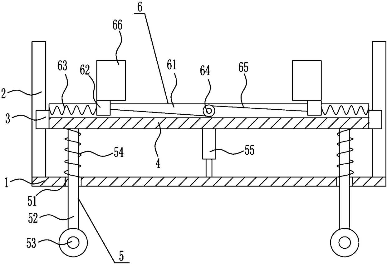
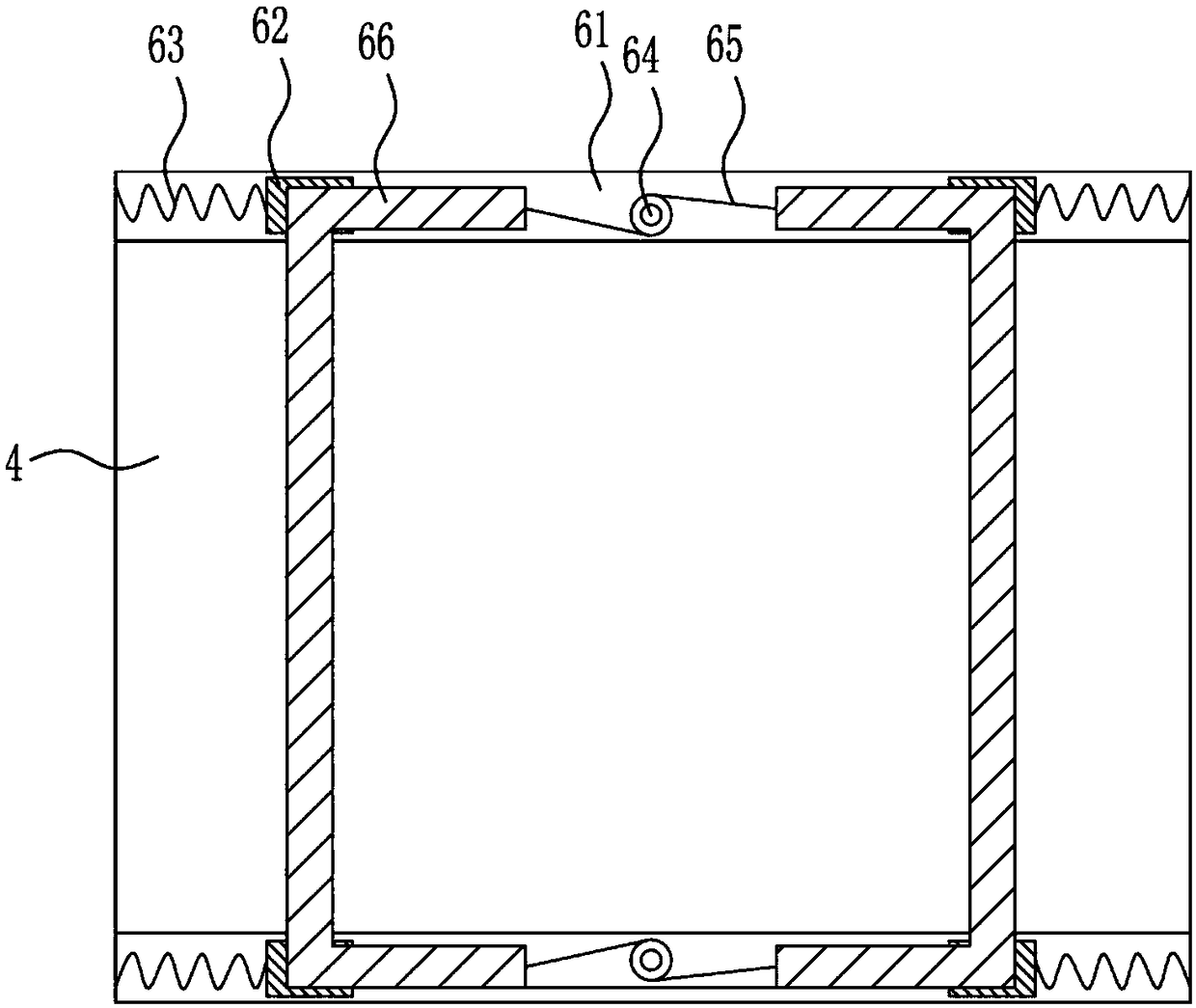
[0029] A fixed base for installation of a power cabinet, such as Figure 1-5 As shown, it includes a base plate 1, a first slide rail 2, a first slide block 3, a placement plate 4, a height adjustment mechanism 5 and a fixing mechanism 6. The top of the base plate 1 is symmetrically provided with a first slide rail 2, and the first slide rail 2 is provided with a first slide block 3, a placement plate 4 is connected between the left and right first slide blocks 3, a height adjustment mechanism 5 is provided on the bottom plate 1, and a fixing mechanism 6 is provided on the top of the placement plate 4.
Embodiment 2
[0031] A fixed base for installation of a power cabinet, such as Figure 1-5 As shown, it includes a base plate 1, a first slide rail 2, a first slide block 3, a placement plate 4, a height adjustment mechanism 5 and a fixing mechanism 6. The top of the base plate 1 is symmetrically provided with a first slide rail 2, and the first slide rail 2 is provided with a first slide block 3, a placement plate 4 is connected between the left and right first slide blocks 3, a height adjustment mechanism 5 is provided on the bottom plate 1, and a fixing mechanism 6 is provided on the top of the placement plate 4.
[0032] The height adjustment mechanism 5 comprises guide rod 52, wheel 53, first spring 54 and electric push rod 55, has guide hole 51 on the bottom plate 1, is provided with guide rod 52 in the guide hole 51, guide rod 52 tops and placement plate 4 The bottom is connected, the bottom end of the guide rod 52 is connected with a wheel 53, a first spring 54 is provided between t...
Embodiment 3
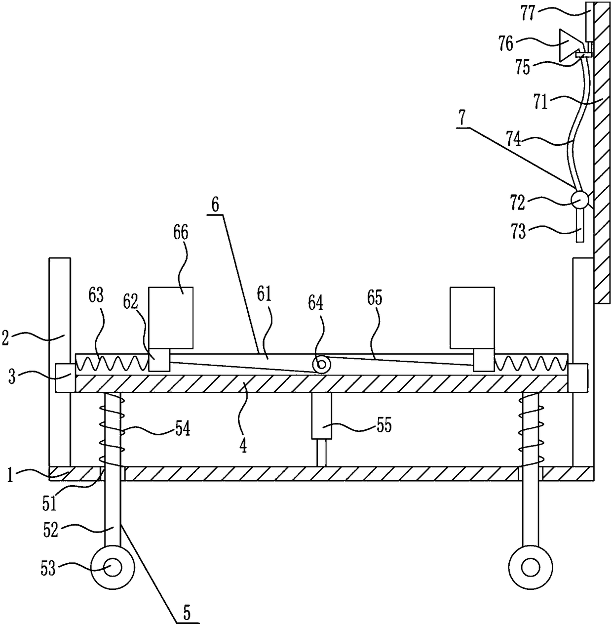
[0034] A fixed base for installation of a power cabinet, such as Figure 1-5 As shown, it includes a base plate 1, a first slide rail 2, a first slide block 3, a placement plate 4, a height adjustment mechanism 5 and a fixing mechanism 6. The top of the base plate 1 is symmetrically provided with a first slide rail 2, and the first slide rail 2 is provided with a first slide block 3, a placement plate 4 is connected between the left and right first slide blocks 3, a height adjustment mechanism 5 is provided on the bottom plate 1, and a fixing mechanism 6 is provided on the top of the placement plate 4.
[0035] The height adjustment mechanism 5 comprises guide rod 52, wheel 53, first spring 54 and electric push rod 55, has guide hole 51 on the bottom plate 1, is provided with guide rod 52 in the guide hole 51, guide rod 52 tops and placement plate 4 The bottom is connected, the bottom end of the guide rod 52 is connected with a wheel 53, a first spring 54 is provided between t...
PUM
 Abstract
Description
Claims
Application Information
 - R&D
- Intellectual Property
- Life Sciences
- Materials
- Tech Scout
- Unparalleled Data Quality
- Higher Quality Content
- 60% Fewer Hallucinations
Browse by: Latest US Patents, China's latest patents, Technical Efficacy Thesaurus, Application Domain, Technology Topic, Popular Technical Reports.
© 2025 PatSnap. All rights reserved.Legal|Privacy policy|Modern Slavery Act Transparency Statement|Sitemap|About US| Contact US: help@patsnap.com


