
A Deformable Wing Mechanism Based on Scissor Linkage Skeleton and Sliding Skin

A technology of deforming wings and linkage, applied in directions such as wing adjustment, can solve the problems of single deformation function, inability to realize the folding of rigid skin of wings, etc., and achieve the effects of low manufacturing cost, simple structure, and convenient production and installation.

Active Publication Date: 2021-04-02
HARBIN INST OF TECH
View PDF5 Cites 0 Cited by
  • Summary
  • Abstract
  • Description
  • Claims
  • Application Information

AI Technical Summary

Problems solved by technology

[0006] The purpose of the present invention is to solve the problem that the existing deformed wing has a single deformation function, and can only realize one of variable sweep, variable area and variable length, and cannot realize the folding of the rigid skin of the wing, and then provide a A Deformable Wing Mechanism Based on Scissor Linkage Skeleton and Sliding Skin

Method used


Image

  • A Deformable Wing Mechanism Based on Scissor Linkage Skeleton and Sliding Skin
  • A Deformable Wing Mechanism Based on Scissor Linkage Skeleton and Sliding Skin
  • A Deformable Wing Mechanism Based on Scissor Linkage Skeleton and Sliding Skin

Examples


specific Embodiment approach 1

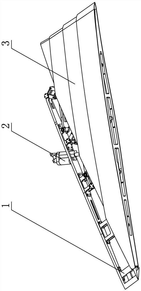
[0035] Embodiment 1: Combining figure 1 Describing this embodiment, a deformable wing mechanism based on a scissor linkage frame and a sliding skin in this embodiment includes a scissor linkage frame 1, a driving device and a sliding skin 3 installed outside the scissor linkage frame 1, The sliding skin 3 is fixedly installed on the scissor linkage frame 1. The scissors linkage frame 1 drives the sliding skin 3 to fold or unfold layer by layer. The driving device drives the scissor linkage frame 1 to fold and unfold the entire deformation wing mechanism.

specific Embodiment approach 2

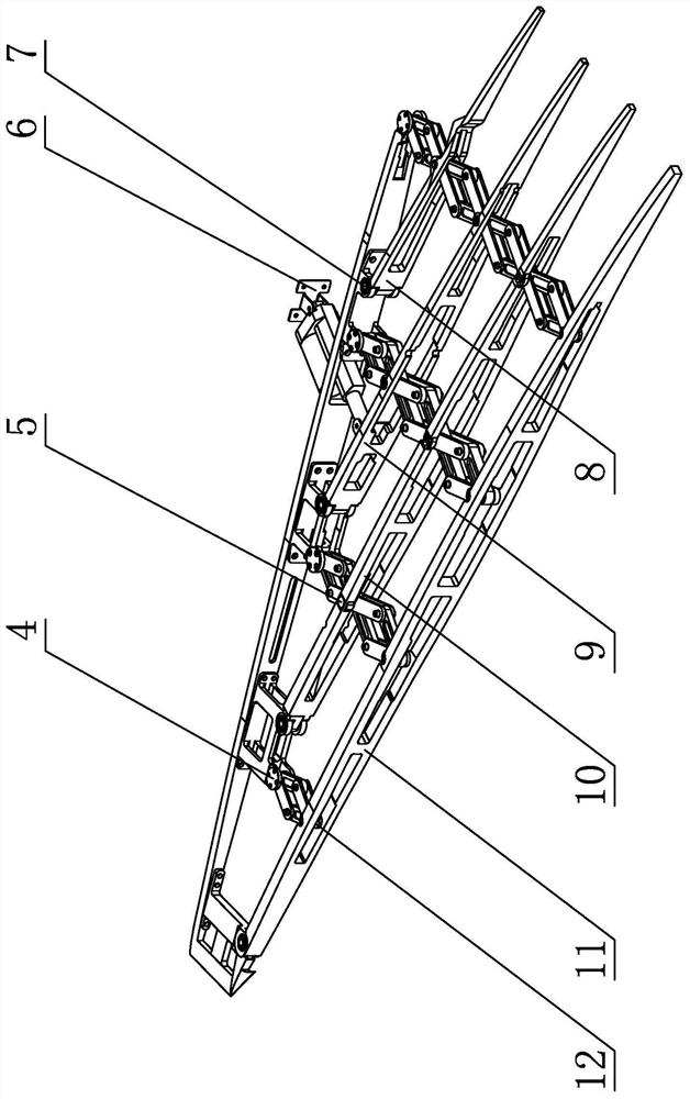
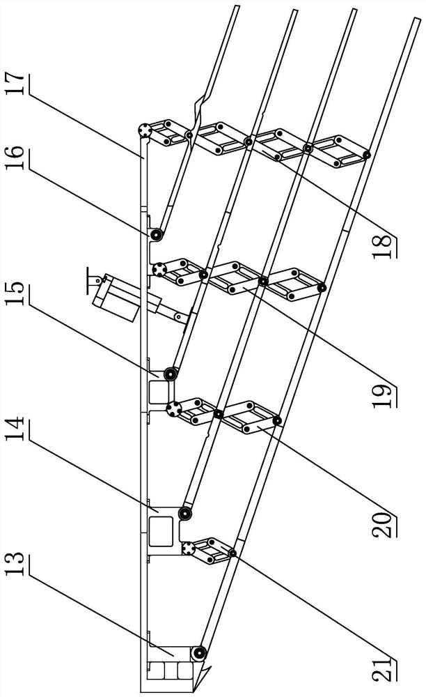
[0036] Specific implementation mode 2: Combining Figure 1 to Figure 4Describing this embodiment, the scissor linkage frame 1 of this embodiment includes a support seat 17, N bases, N support frames and N groups of scissor hinge units of different lengths (the number of N can be selected according to the requirements of the wingspan area, using Modular design, the larger the wing area, the larger the N),

[0037] The N bases include a first base 13 , a second base 14 , a third base 15 , a fourth base 16 , . 17 on,

[0038] The N supporting frames include a first supporting frame 11 , a second supporting frame 10 , a third supporting frame 9 , a fourth supporting frame 8 , . It is sequentially connected with the corresponding first base 13 to the Nth base in rotation, and the N supporting frames are arranged in parallel.

[0039] The N groups of shear hinge units include a first shear hinge unit 21 , a second shear hinge unit 20 , a third shear hinge unit 19 , a fourth shear...

specific Embodiment approach 3

[0045] Specific implementation three: combination figure 2 Describing this embodiment, the scissor linkage frame 1 of this embodiment further includes N first hinges 4 , and N groups of scissor hinge units are respectively hinged to the support base 17 or the corresponding base through the N first hinges 4 . With this arrangement, coordinated deformation of the scissor linkage frame 1 can be achieved. Other compositions and connection relationships are the same as in the first or second embodiment.


PUM


Abstract

The invention provides a variable wing mechanism based on a shears-fork linkage framework and a sliding skin and relates to the technical field of aerospace devices and equipment, aiming at solving the problems of an existing variable wing that the variable function is single, only one variation of variable sweepback, variable area and variable elongation can be realized, and rigid skin folding ofa wing cannot be realized. The variable wing mechanism comprises the shears-fork linkage framework, a driving device and the sliding skin mounted at the outer part of the shears-fork linkage framework; the sliding skin is fixedly mounted on the shears-fork linkage framework; the shears-fork linkage framework drives the sliding skin to realize layer-by-layer folding or unfolding; the driving device drives the shears-fork linkage framework to realize folding or unfolding of the whole variable wing mechanism. According to the mechanism provided by the invention, wing elongation length, area andsweepback angles can be changed through the movement of the mechanism. The variable wing mechanism can be used for the variation of wing parts of an aircraft. The variable wing mechanism can be used for wing structures of various variable wing aircrafts.

Description

technical field [0001] The invention relates to the technical field of aerospace equipment and equipment, in particular to a deformable wing mechanism based on a scissor linkage skeleton and a sliding skin. Background technique [0002] Because the geometry of traditional aircraft is basically fixed, its system model is basically fixed. In the same atmospheric environment, it can only do some specific flights and complete some special tasks. With the increasing complexity of the application of aircraft in the military and civil fields, there is an urgent need for an aircraft that can have a larger flight airspace and speed domain, can take into account both high and low altitudes, high and low speeds, and even take off from the ground and fly through the atmosphere to perform various Aircraft for complex missions such as reconnaissance and strike. It is difficult for traditional aircraft to adapt to such a wide range of flight environment parameters and maintain excellent p...

Claims


Application Information

Patent Timeline
Patent Type & Authority Patents(China)
IPC IPC(8): B64C3/40B64C3/54
CPCB64C3/40B64C3/54
Inventor 郭宏伟杨皓宇张祖豪邓宗全李兵
Owner HARBIN INST OF TECH
Learn More