Multifunctional chair

A technology of multifunctional chairs and rotating shafts, applied in the field of chairs, can solve the problems of high sales price, limited use space, complex structure, etc., and achieve the effects of reducing wood consumption, convenient and fast handling, and simple changing methods

Inactive Publication Date: 2018-06-15
魏铃杰
View PDF0 Cites 2 Cited by
  • Summary
  • Abstract
  • Description
  • Claims
  • Application Information

AI Technical Summary

Problems solved by technology

There are also chairs that can change the shape on the market, and the sitting and standing shape can be changed into a lying and lying shape that can satisfy lying and lying. However, this kind of chair has a complex structure, high cost, and correspondingly high sales price, so it is difficult to popularize and use it on a large scale.
There are also some chairs whose shape can be changed, their volume is large, and the floor area is large, which makes the use of space limited.
In addition, such chairs are heavy, making it difficult to move and carry easily and quickly

Method used


Image

  • Multifunctional chair
  • Multifunctional chair
  • Multifunctional chair

Examples


Embodiment 1

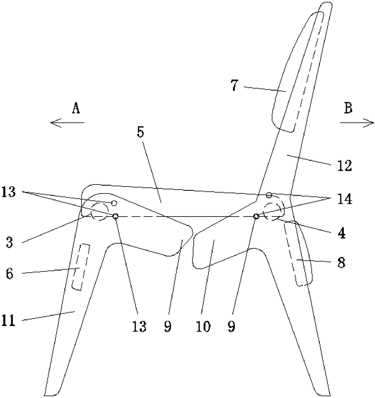
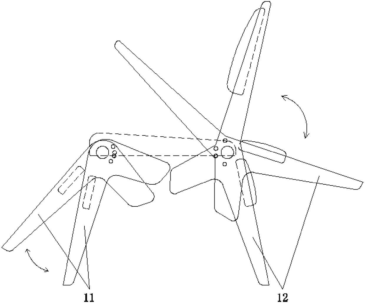
[0038] Embodiment one: if Figure 1 to Figure 4As shown, the present embodiment provides a multifunctional chair, including a first support group 1 , a second support group 2 , a first rotating shaft 3 , a second rotating shaft 4 and a seat board 5 . In this embodiment, direction A indicates the front, and direction B indicates the rear. The two ends of the first rotating shaft 3 are respectively connected to the tops of the two first supports 11 of the first support group 1, and the first rotating shaft 3 is located between the two first supports 11, so that the two first supports 11 Symmetrical distribution. A reinforcing plate 6 is arranged between the supports. The reinforcing plate 6 improves the stability of the structure of the first support group 1 and improves its load-bearing capacity. The two ends of the second rotating shaft 4 are respectively connected with the middle part of the two second supports 12 of the second support group 2, and the second rotating shaf...

Embodiment 2

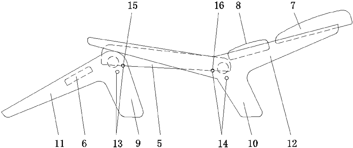
[0045] Embodiment two: if Figure 5 to Figure 15 As shown, most of the structures of the second embodiment are the same as those of the first embodiment, the difference is that in this embodiment, in order to achieve locking, the seat board 5 is detachably connected to the first rotating shaft 3 and the second rotating shaft 4 respectively. The first rotating shaft 3 is fixedly connected to the first bracket group 1, and the second rotating shaft 4 is fixedly connected to the second bracket group 2. The seat plate 5 is provided with a first mounting groove corresponding to the first rotating shaft 3, and a second mounting groove corresponding to the second rotating shaft 4, and a group of first positioning pin groups are arranged in the first mounting groove, and the first positioning pin group is arranged in the first mounting groove. The positioning pin set includes two first positioning pins 19 . The two first positioning pins 19 of the first positioning pin group are clos...


PUM


Abstract

The invention discloses a multifunctional chair. The multifunctional chair comprises a first support group, a second support group, a first rotating shaft, a second rotating shaft and a seat board, wherein two ends of the first rotating shaft are respectively connected with the upper parts of two first supports of the first support group; in addition, the first rotating shaft is positioned betweenthe two first supports; two ends of a second rotating shaft are respectively connected with the middle parts of two second supports of the second support group; the second rotating shaft is positioned between the two second supports; a first bump group is arranged at the upper part of the first support group; a second bump group is arranged at the middle part of the second support group; the seatboard is arranged on the first rotating shaft and the second rotating shaft. The multifunctional chair disclosed by the invention has the advantages that the structure of the chair is optimized, theconsumption of wood is reduced and the protection for the environment is improved; meanwhile, the occupied area is reduced, the weight is reduced, and movement and transportation are facilitated.

Description

technical field [0001] The invention relates to the technical field of chairs, in particular to a multifunctional chair. Background technique [0002] In today's tight pace of life, whether it is work or leisure, people are always inseparable from the need for "lying", especially after a busy day, they have a strong desire to lie down and relax. In fact, it is not difficult to find that people always have to lie down in response to their physical or psychological needs, whether in office, study or entertainment. Especially in some special places such as companies and units, it is expressly forbidden to carry and use recliners. It has become a luxury for people. [0003] Most of the current chairs have only one form, which is the sitting and standing form when sitting and standing are satisfied. There are also chairs in the market that can change the shape, and the sitting and standing shape can be changed into a lying shape that can satisfy lying and lying. However, this k...

Claims


Application Information

Patent Timeline
Patent Type & Authority Applications(China)
IPC IPC(8): A47C1/028A47C1/029A47C1/024A47C1/14
CPCA47C1/028A47C1/024A47C1/029A47C1/14
Inventor 魏铃杰
Owner 魏铃杰
Why Eureka
Try Eureka