Special pregnant woman or puerpera transfer rehabilitation device for obstetrical department
A rehabilitation device and technology for pregnant women, applied in the directions of transportation and packaging, friction resistance devices, sports accessories, etc., can solve the problems of increasing labor intensity and workload of medical staff, affecting the health of pregnant women and infants, and adjusting the lifting height by manpower. The effect of work load, safety and health, and high comfort
- Summary
- Abstract
- Description
- Claims
- Application Information
AI Technical Summary
Problems solved by technology
Method used
Image
Examples
Embodiment 1
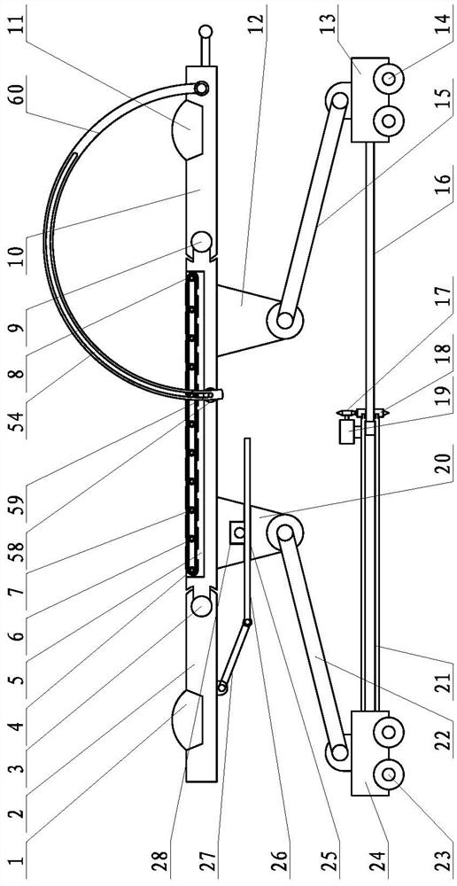
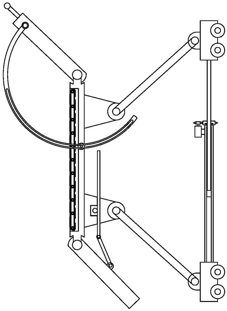
[0038] Such as figure 1 with 2 As shown, a special obstetric pregnant woman or puerpera transfer rehabilitation device according to the present invention includes a support plate and a lifting support frame. The lower bottom surface of the support plate is respectively provided with a front left hinge support, a front right hinge support, and a rear left hinge Seat and rear right hinged support; the lifting support frame includes front left hinged rod, front right hinged rod, rear left hinged rod, rear right hinged rod and telescopic bottom frame structure; the support plate passes through the front left hinged The articulated support, the rear left articulated support and the rear right articulated support respectively correspond to the upper ends of the front left articulated rod, the front right articulated rod, the rear left articulated rod and the rear right articulated rod which are hingedly connected to the elevating support frame; The lower ends of the left articulate...
Embodiment 2
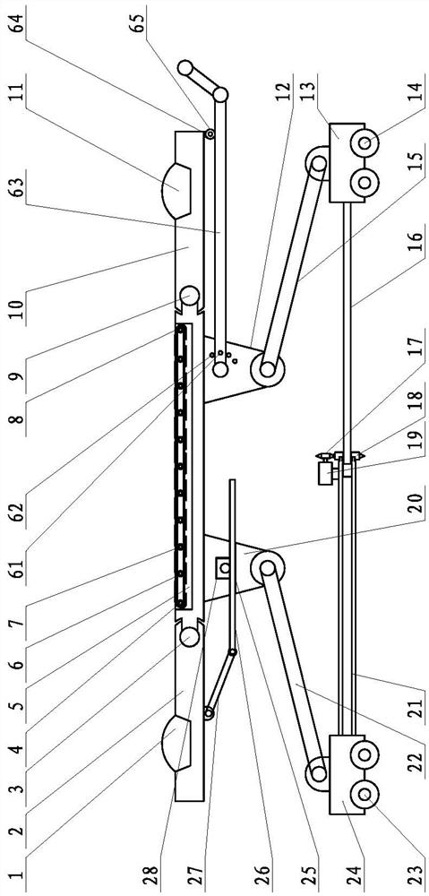
[0054] Such as image 3 with4 As shown, in this embodiment, the front support adjustment device includes a "Π" shaped push rod, the push rod includes a left push rod cantilever, a right push rod cantilever and a push rod cross arm, a left push rod cantilever and a right push rod The front end of the rod cantilever is vertically connected to the two ends of the push rod cross arm; the rear ends of the left push rod cantilever and the right push rod cantilever are hinged and fixed to the front left hinged support through the left push rod cantilever hinge shaft and the right push rod cantilever hinge shaft respectively and the outer side of the front right hinged support; the left pulley guide groove and the right pulley guide groove are set on the upper surface of the left push rod cantilever and the right push rod cantilever respectively; The left front plate guide pulley and the right front plate guide pulley are respectively installed, and the left front plate guide pulley a...
Embodiment 3
[0058] Such as Figure 6-9 As shown, in the example of this city, the lower limb exercise device is installed on the rear plate, and the exercise device container with the rear end open is set on the rear plate, and the lower limb exercise device is arranged in the exercise device container;
[0059] The lower limb exercise device includes a first rotating shaft cylinder with an open rear end, and the front end of the first rotating shaft cylinder is closed and hinged to the front end of the movement device's containing groove. Install a support block on the side wall of the first rotating shaft cylinder, and hinge one end of the supporting roller in the kinematic installation groove. When the first rotating shaft cylinder rotates to a vertical state, the other end of the supporting roller can press against and support the first rotating shaft cylinder The lower part of the supporting block keeps the first rotating shaft cylinder in a vertical state. It also includes a liftin...
PUM
 Abstract
Description
Claims
Application Information
 - R&D
- Intellectual Property
- Life Sciences
- Materials
- Tech Scout
- Unparalleled Data Quality
- Higher Quality Content
- 60% Fewer Hallucinations
Browse by: Latest US Patents, China's latest patents, Technical Efficacy Thesaurus, Application Domain, Technology Topic, Popular Technical Reports.
© 2025 PatSnap. All rights reserved.Legal|Privacy policy|Modern Slavery Act Transparency Statement|Sitemap|About US| Contact US: help@patsnap.com


