Automatic three-level lifting paint spraying device for gallery bridge

A kind of painting equipment and automatic technology, which is applied in the direction of construction and building structure, and can solve the problems of high-level paint contamination, long working hours, and low efficiency of corridor bridges

Active Publication Date: 2018-06-15
嵊州市旭辉建材有限公司
View PDF6 Cites 4 Cited by
  • Summary
  • Abstract
  • Description
  • Claims
  • Application Information

AI Technical Summary

Problems solved by technology

[0003] At present, when repainting and maintaining the corridor bridge, most of them use manual hand-held brushes and paint buckets to spray paint on the corridor bridge, which leads to too long working hours, and it is difficult for traditional manual labor to repaint the high places of the corridor bridge. Spraying paint, resulting in long work, slow speed and low efficiency, and the paint will also be stained on the workers' clothes during the painting process
[0004] Therefore urg

Method used


Image

  • Automatic three-level lifting paint spraying device for gallery bridge
  • Automatic three-level lifting paint spraying device for gallery bridge
  • Automatic three-level lifting paint spraying device for gallery bridge

Examples


Embodiment 1

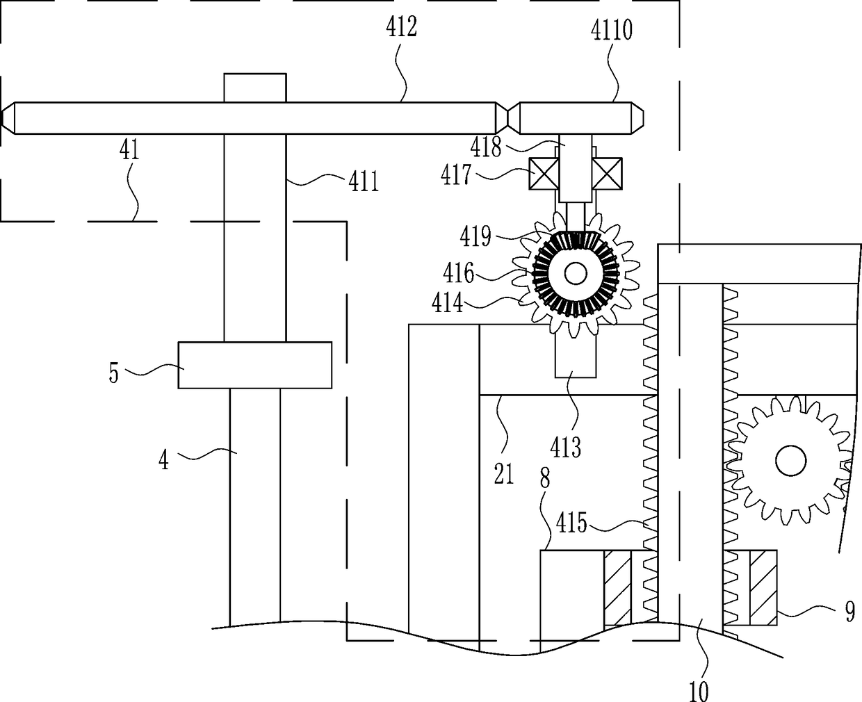
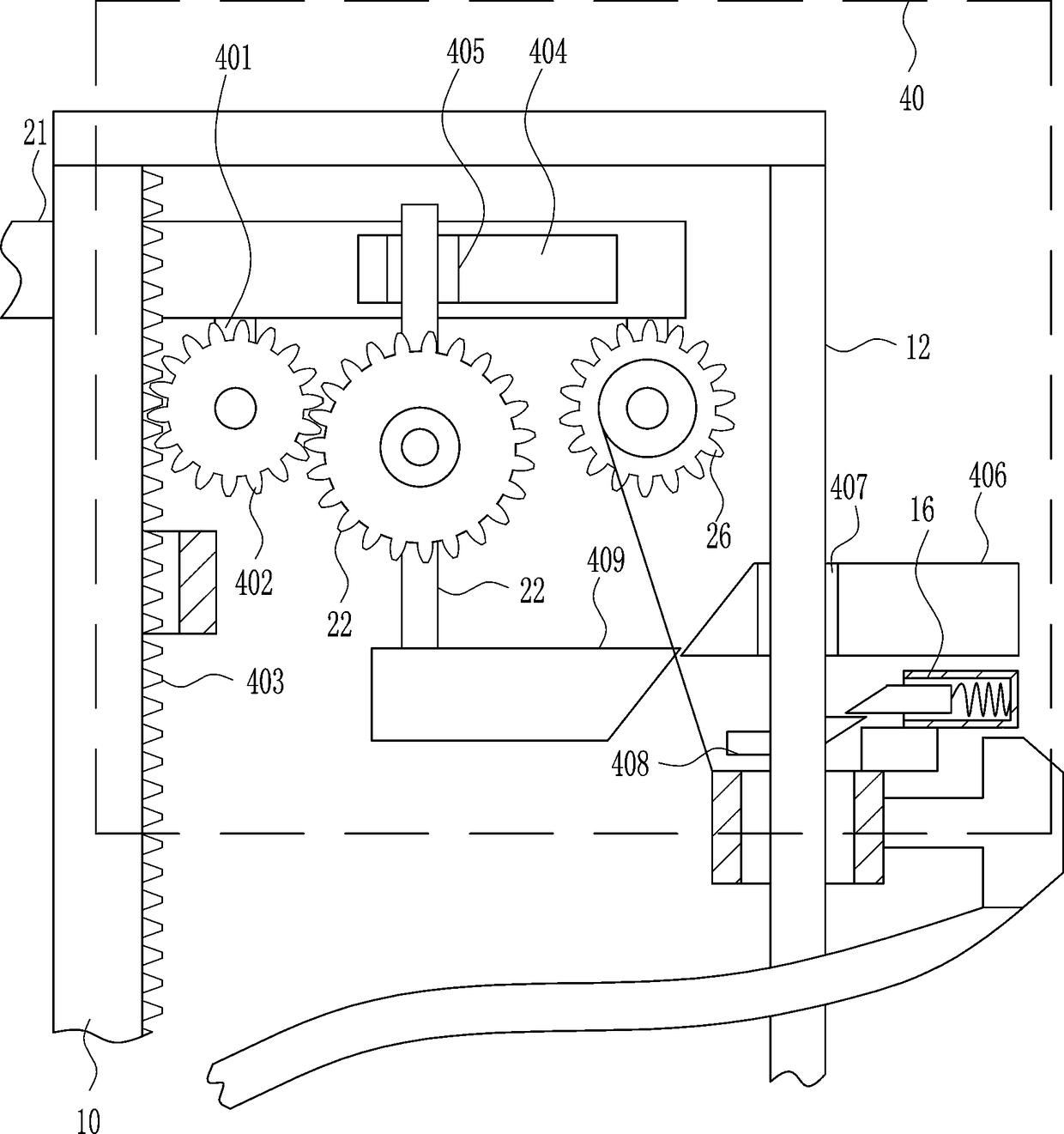
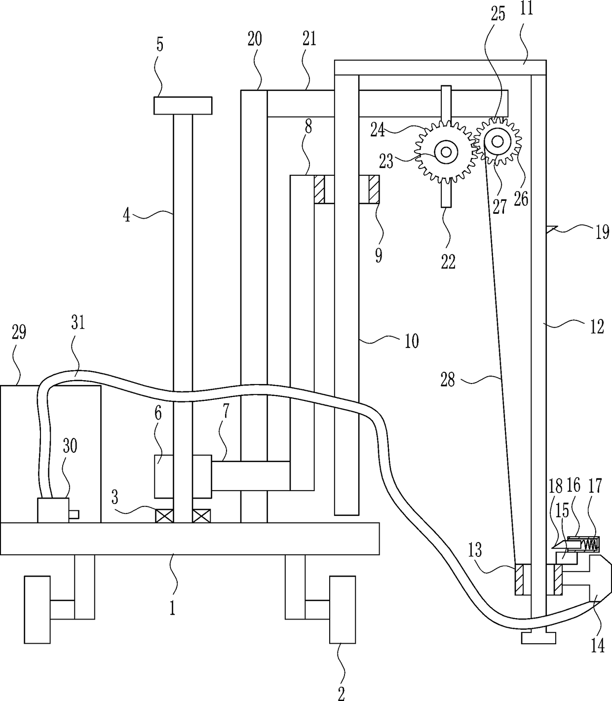
[0028] An automatic three-stage lifting painting equipment for corridor bridges, such as Figure 1-5 As shown, it includes a fixed plate 1, a wheel 2, a first bearing seat 3, a screw mandrel 4, a handle 5, a nut 6, a connecting block 7, a first connecting rod 8, a first guide sleeve 9, a first guide rail 10, The second connecting rod 11, the second guide rail 12, the second guide sleeve 13, the nozzle 14, the installation block 15, the positioning sleeve 16, the first spring 17, the first cone block 18, the second cone block 19, the installation rod 20, the installation Plate 21, support rod 22, electric wheel 23, first gear 24, first fixed block 25, second gear 26, winding wheel 27, pull wire 28, paint box 29, water pump 30 and infusion tube 31, fixed plate 1 The side is connected with the wheel 2, the middle part of the upper side of the fixed plate 1 is connected with the first bearing seat 3, the first bearing seat 3 is connected with the screw rod 4, the upper end of the ...

Embodiment 2

[0030] An automatic three-stage lifting painting equipment for corridor bridges, such as Figure 1-5 As shown, it includes a fixed plate 1, a wheel 2, a first bearing seat 3, a screw mandrel 4, a handle 5, a nut 6, a connecting block 7, a first connecting rod 8, a first guide sleeve 9, a first guide rail 10, The second connecting rod 11, the second guide rail 12, the second guide sleeve 13, the nozzle 14, the installation block 15, the positioning sleeve 16, the first spring 17, the first cone block 18, the second cone block 19, the installation rod 20, the installation Plate 21, support rod 22, electric wheel 23, first gear 24, first fixed block 25, second gear 26, winding wheel 27, pull wire 28, paint box 29, water pump 30 and infusion tube 31, fixed plate 1 The side is connected with the wheel 2, the middle part of the upper side of the fixed plate 1 is connected with the first bearing seat 3, the first bearing seat 3 is connected with the screw rod 4, the upper end of the ...

Embodiment 3

[0033] An automatic three-stage lifting painting equipment for corridor bridges, such as Figure 1-5As shown, it includes a fixed plate 1, a wheel 2, a first bearing seat 3, a screw mandrel 4, a handle 5, a nut 6, a connecting block 7, a first connecting rod 8, a first guide sleeve 9, a first guide rail 10, The second connecting rod 11, the second guide rail 12, the second guide sleeve 13, the nozzle 14, the installation block 15, the positioning sleeve 16, the first spring 17, the first cone block 18, the second cone block 19, the installation rod 20, the installation Plate 21, support rod 22, electric wheel 23, first gear 24, first fixed block 25, second gear 26, winding wheel 27, pull wire 28, paint box 29, water pump 30 and infusion tube 31, fixed plate 1 The side is connected with the wheel 2, the middle part of the upper side of the fixed plate 1 is connected with the first bearing seat 3, the first bearing seat 3 is connected with the screw rod 4, the upper end of the s...


PUM


Abstract

The invention relates to a gallery bridge maintenance device, in particular to an automatic three-level lifting paint spraying device for a gallery bridge. The automatic three-level lifting paint spraying device for the gallery bridge can paint spraying on the upper portion of the gallery bridge, and avoid the cloth of the workers from getting stained by paint during the painting process. The automatic three-level lifting paint the spraying device for gallery bridge comprises a fixing plate, wheels, a first bearing seat, a screw rod, a crank, a nut, a connecting block, a first connecting, a first guide sleeve, a first guide rail, a second connecting rod and the like; wheels are connected on the lower side of the fixing plate, and the first bearing seat is connected on the middle portion ofthe upper side of the fixing plate; the screw rod is connected in the first bearing seat, and the crank is connected on the upper end of the screw rod; and the nut is screwed on the lower side of thescrew rod, and the nut is matched with the screw rod. The automatic three-level lifting paint spraying device for the gallery bridge achieves the effects that the high portion of the gallery bridge can be painted, and the clothes of the workers are not stained by paint during the painting process.

Description

technical field [0001] The invention relates to maintenance equipment for corridor bridges, in particular to an automatic three-stage lifting painting equipment for corridor bridges. Background technique [0002] As the name suggests, "covered bridge" is a bridge with eaves. In Taishun in history, the villages were scattered and the traffic was remote. It is difficult for people to see people when they walk for more than ten miles. According to the "traffic planning" of Taishun ancestors, a wind and rain pavilion should be built for people to rest on the side of the road (stone road) separated by a certain mile. The eaves built on the bridge can not only protect the wooden bridge from the sun and rain, but also play the role of a wind and rain pavilion. Some covered bridges also have rooms for people to live temporarily. [0003] At present, when repainting and maintaining the corridor bridge, most of them use manual hand-held brushes and paint buckets to spray paint on ...

Claims


Application Information

Patent Timeline
IPC IPC(8): E04F21/12
Inventor 张梦君李仔敏汤蒙琪
Owner 嵊州市旭辉建材有限公司
Why Eureka
Try Eureka