
An electric power supply plug-in device

A plug-in device and electric power supply technology, which is applied to two-part connection devices, parts of connection devices, coupling devices, etc., can solve problems such as loose connection, no installation, and the risk of electric shock, so as to achieve the goal of not easy to disengage and reduce the risk of electric shock. effect of influence

Inactive Publication Date: 2019-07-26
石狮领顺能源科技有限公司
View PDF7 Cites 0 Cited by
  • Summary
  • Abstract
  • Description
  • Claims
  • Application Information

AI Technical Summary

Problems solved by technology

[0002] Power supply devices are often used in the field of electricity. In some electric equipment, the power components in the power equipment are often powered by the connection of plugs and sockets. Therefore, the stability of the connection between plugs and sockets is the key to determine whether the power components can operate normally. , in the prior art, the plug is generally inserted into the socket to carry out power supply. Since there is no locking structure between the plug and the socket, it is easy to cause the connection to be loose, so that the power components in the power equipment cannot be supplied normally, which is not only serious It affects the power supply, and it is very easy to cause the risk of electric shock when it is loose, and there is a big safety hazard. For this reason, we propose a power supply plug-in device to solve the above problems

Method used


Image

  • An electric power supply plug-in device
  • An electric power supply plug-in device
  • An electric power supply plug-in device

Examples


Embodiment Construction

[0023] The following will clearly and completely describe the technical solutions in the embodiments of the present invention with reference to the accompanying drawings in the embodiments of the present invention. Obviously, the described embodiments are only some, not all, embodiments of the present invention. Based on the embodiments of the present invention, all other embodiments obtained by persons of ordinary skill in the art without making creative efforts belong to the protection scope of the present invention.

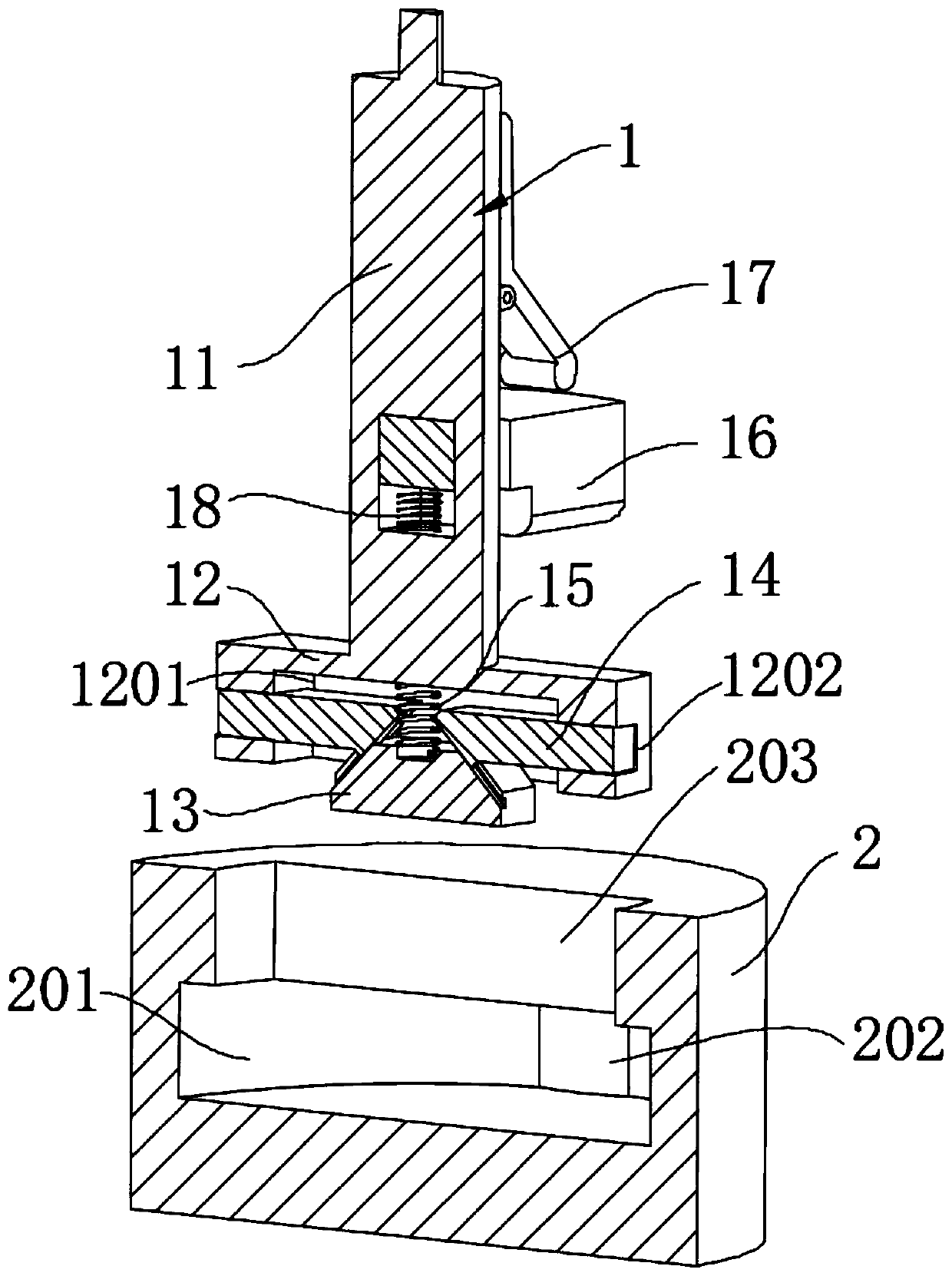
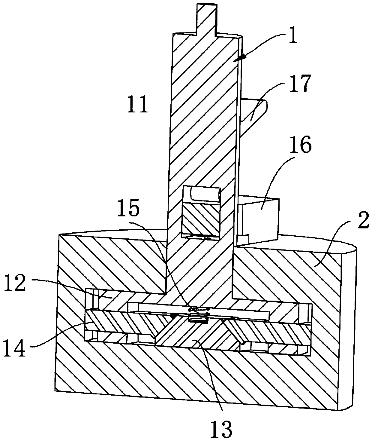
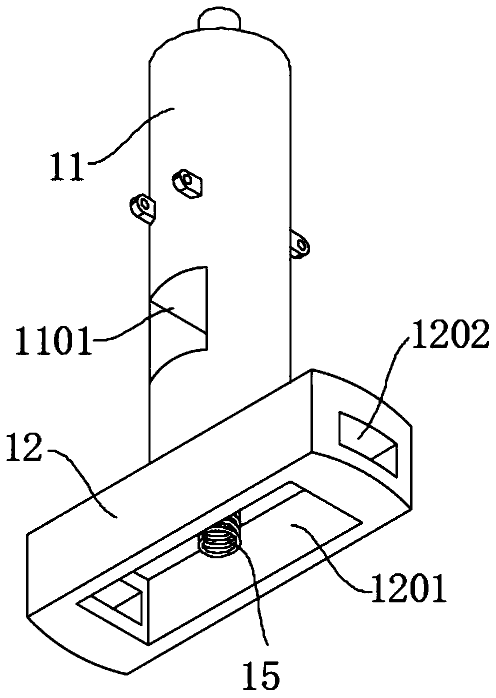
[0024] see Figure 1-7 , the present invention provides a technical solution: a power supply plug-in device, including a plug 1 and a socket 2, the plug 1 includes a plug hand piece 11, a blade box 12, a wedge 13 and a blade 14, and the blade box 12 is fixed Installed on the lower end of the plug hand piece 11, the insert box 12 is provided with an insert cavity 1201, and the top of the insert cavity 1201 is elastically connected with a wedge 13, and the top o...


PUM


Abstract

The invention discloses an electric power supply inserting-connecting apparatus. The electric power supply inserting-connecting apparatus comprises a plug and a socket; the plug comprises a plug hand-held part, an inserting sheet box, a wedge-shaped block and inserting sheets; the inserting sheet box is fixedly mounted at the lower end of the plug hand-held part; an inserting sheet cavity is formed in the inserting sheet box; the inner top end of the inserting sheet cavity is elastically connected with the wedge-shaped block; the two ends of the wedge-shaped block are glidingly clamped with two inserting sheets through a key slot structure; the two inserting sheets run through the two ends of the inserting sheet box respectively; the inserting sheet box movably runs through a through holein the top end of the socket; a contact piece groove is formed in the socket at the lower end of the through hole; and contact pieces are fixed at the two ends of the contact piece groove. Through limiting rods, up and down movement of positioning blocks can be controlled; the limiting rods perform downward thrust on the positioning blocks under the effect of a torsional spring, wherein the thrustis greater than sum of elastic force provided by a spring and a compression spring, so that the positioning blocks can be tightly extruded and pressed at the top end of the socket, and sliding of theplug can be avoided; and therefore, only when the symmetrical limiting rods are pressed downwards, the plug can be inserted into the socket, so that a certain protection effect is achieved.

Description

technical field [0001] The invention relates to the technical field of electric equipment, in particular to an electric power supply plug-in device. Background technique [0002] Power supply devices are often used in the field of electricity. In some electric equipment, the power components in the power equipment are often powered by the connection of plugs and sockets. Therefore, the stability of the connection between plugs and sockets is the key to determine whether the power components can operate normally. , in the prior art, the plug is generally inserted into the socket to carry out power supply. Since there is no locking structure between the plug and the socket, it is easy to cause the connection to be loose, so that the power components in the power equipment cannot be supplied normally, which is not only serious The power supply is affected, and it is very easy to cause the risk of electric shock when it is loose, and there is a big safety hazard. Therefore, we p...

Claims


Application Information

Patent Timeline
Patent Type & Authority Patents(China)
IPC IPC(8): H01R13/44H01R13/502H01R13/60H01R13/625H01R13/633H01R13/639H01R24/00
CPCH01R13/44H01R13/502H01R13/60H01R13/625H01R13/6335H01R13/639H01R24/005
Inventor 魏亮
Owner 石狮领顺能源科技有限公司
Learn More