Retrieval systems and methods for use thereof

a technology applied in the field of retrieval systems and methods for use thereof, can solve the problems of limited ability of the device to constrain into a reduced profile, lack of oxygen and nutrients to the brain tissue, and limited access by the physician to remote regions, so as to prevent the migration of obstructions, increase the effectiveness of removing obstructions, and hinder the ability of the practitioner to remov

Active Publication Date: 2014-08-12
COVIDIEN LP
View PDF267 Cites 86 Cited by
  • Summary
  • Abstract
  • Description
  • Claims
  • Application Information

AI Technical Summary

Benefits of technology

[0025]As noted herein, the joint-less construction improves the flexibility and strength of the device by eliminating joints, connection points, or other attachment points. In addition, the joint-less construction improves the ability of the device to be delivered through a small microcatheter. As a result, the device and microcatheter are able to access remote regions of the vasculature.
[0027]The devices of the present invention may also include features to prevent migration of the obstruction as the capturing portion encapsulates the obstruction. For example, a proximal foot (such as region of increased surface area) can be located on or in the catheter. In another variation, an additional capture portion is located on the catheter where the proximal end of this capture is a mesh, a single wound wire, a film, a membrane, a polymer covering, or a plurality of crossing wires affixed to or in the catheter. Accordingly, the capturing portions both envelope or surround the obstruction as they are moved together. As noted below, additional variations may allow for temporarily locking of the two capturing portions together for increase effectiveness in removing the obstruction from the body.
[0028]The capturing portions disclosed herein can include mechanical features that assist in removal of the obstruction. These features can be hooks, fibers, barb, or any such structure. Any portion of the capturing portion or even the device can have such hooks, fibers, or barbs that grip into the obstruction as the device surrounds the obstruction. It will be important that such features prevent the obstruction from sliding proximally but do not hinder the ability of the practitioner to remove the device from the body.
[0030]It should be noted that in some variations of the invention, all or some of the device can be designed to increase their ability to adhere to the obstruction. For example, the wires may be coupled to an energy source (e.g., RF, ultrasonic, or thermal energy) to “weld” to the obstruction. Application of energy to the device can allow the surrounding portion to deform into the obstruction and “embed” within the obstruction. Alternatively, the device can impart a positive charge to the obstruction to partially liquefy the obstruction sufficiently to allow for easier removal. In another variation, a negative charge could be applied to further build thrombus and nest the device for better pulling force. The wires can be made stickier by use of a hydrophilic substance(s), or by chemicals that would generate a chemical bond to the surface of the obstruction. Alternatively, the filaments may reduce the temperature of the obstruction to congeal or adhere to the obstruction.

Problems solved by technology

In addition, the degree to which a physician is limited in accessing remote regions of the cerebral vasculature is directly related to the limited ability of the device to constrain into a reduced profile for delivery.
Left untreated, the blockage causes a lack of supply of oxygen and nutrients to the brain tissue.
Blockages that interfere with this supply eventually cause the brain tissue to stop functioning.
If the disruption in supply occurs for a sufficient amount of time, the continued lack of nutrients and oxygen causes irreversible cell death (infarction).
However, these fluids generally take a long time to dissolve clot (sometimes up to several hours).
Thus, the use of these fluids has not been terribly effective at dissolving clot in vessels where a complete blockage occurs.
This minimizes the contact time and amount between the fluid and the clot thereby decreasing the efficiency of the stent and fluid treatment.

Method used


Image

  • Retrieval systems and methods for use thereof
  • Retrieval systems and methods for use thereof
  • Retrieval systems and methods for use thereof

Examples


Embodiment Construction

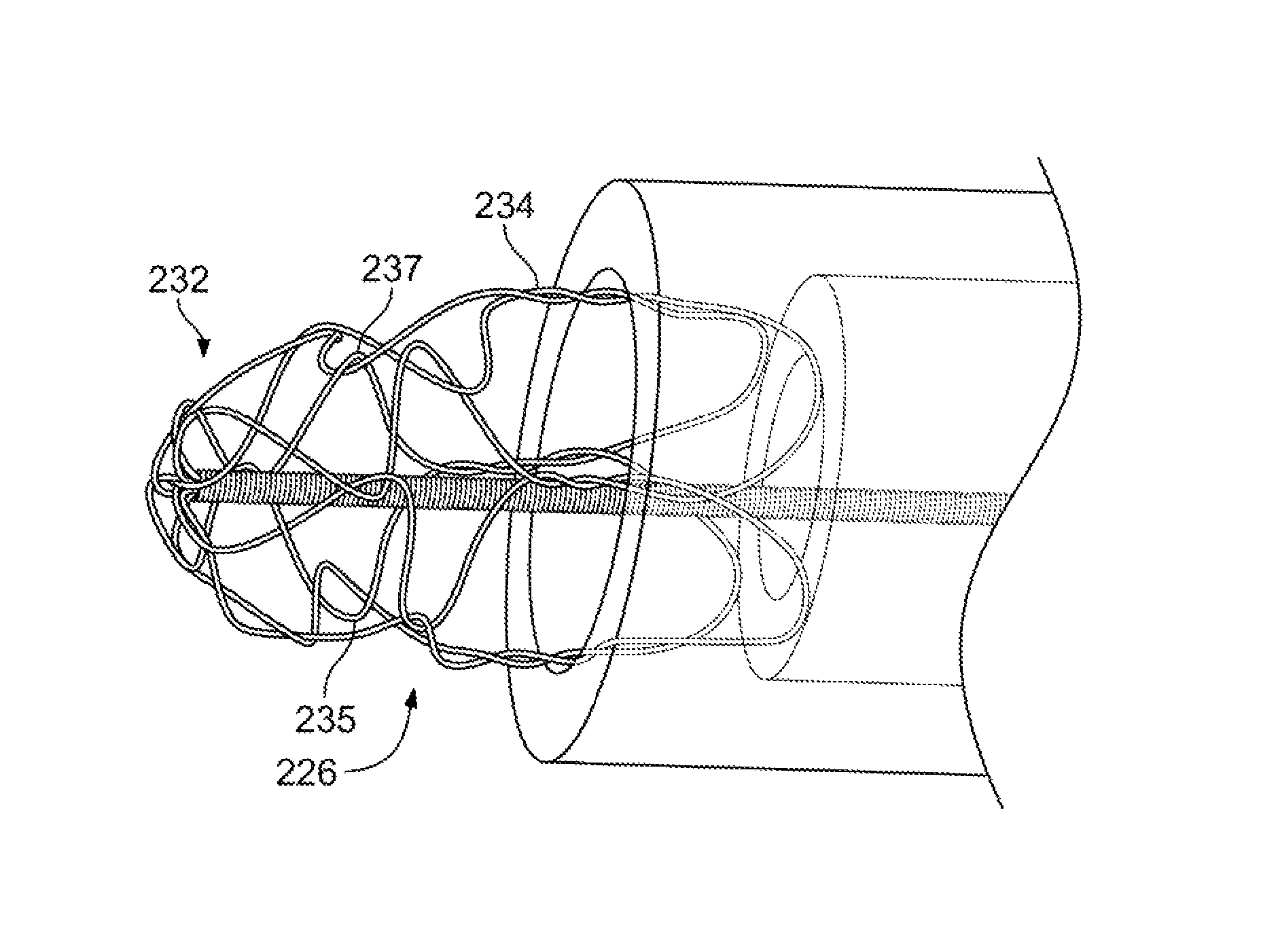
[0061]It is understood that the examples below discuss uses in the cerebral vasculature (namely the arteries). However, unless specifically noted, variations of the device and method are not limited to use in the cerebral vasculature. Instead, the invention may have applicability in various parts of the body. Moreover, the invention may be used in various procedures where the benefits of the method and / or device are desired.

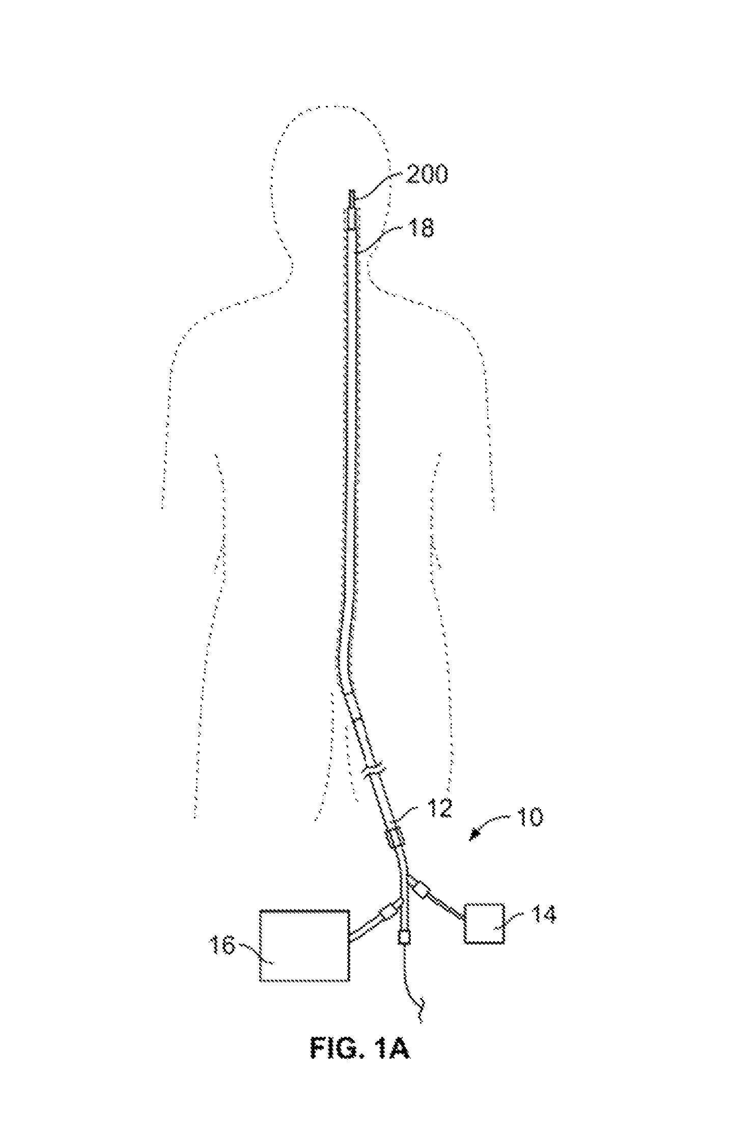
[0062]FIG. 1A illustrates a system 10 for removing obstructions from body lumens as described herein. In the illustrated example, this variation of the system 10 is suited for removal of an obstruction in the cerebral vasculature. Typically, the system 10 includes a catheter 12 microcatheter, sheath, guide-catheter, or simple tube / sheath configuration for delivery of the obstruction removal device to the target anatomy. The catheter should be sufficient to deliver the device as discussed below. The catheter 12 may optionally include an inflatable balloon 18 for t...


PUM


Abstract

The devices and methods described herein relate to improved structures for removing obstructions from body lumens and can include a main bundle comprising a group of wires having a first end and a second end; a capturing portion formed by the group of wires, where the group of wires forming the capturing surface comprise a crossing mesh pattern having a plurality of interference points in the crossing mesh pattern, where the plurality of interference points selectively interfere to limit radial expansion of the capturing surface upon axial compression of the capturing surface. Such devices have applicability in through-out the body, including clearing of blockages within the vasculature.

Description

RELATED APPLICATIONS[0001]This application is a non-provisional of U.S. Provisional Application No. 61 / 297,403 filed Jan. 22, 2010 entitled RETRIEVAL SYSTEMS AND METHODS FOR USE THEREOF, the entirety of which is incorporated by reference.FIELD OF THE INVENTION[0002]The devices described herein are intended to retrieve obstructions from the body. In a first variation, the devices are constructed in wire form where the wires diverge from a main bundle to form a variety of shapes that form a composite device. The benefit of such a diverging wire construction is that the composite complex device can be of a “joint-less” construction. Such devices have applicability through out the body, including clearing of blockages within body lumens, such as the vasculature, by providing a capturing portion that can envelop the obstruction to address the frictional resistance between the obstruction and body lumen prior to attempting to translate and / or mobilize the obstruction within the body lumen...

Claims


Application Information

Patent Timeline
Patent Type & Authority Patents(United States)
IPC IPC(8): A61M29/00A61B17/221A61B17/24A61B17/3207
CPCA61B17/221A61B17/32075A61B17/320725A61B2017/2212A61B2017/320716
Inventor MARTIN, BRIAN, B.
Owner COVIDIEN LP
Why Eureka
Try Eureka