Safety shield

a safety shield and shield technology, applied in the field of safety shields, can solve the problems of inconvenient use of hands by practitioners, inability to protect patients from blood-borne pathogens, and the most prevalent occupational health hazards, so as to prevent hazardous exposure, reduce the occurrence, and reduce the exposure to pathogens.

Active Publication Date: 2007-06-05
KPR U S LLC
View PDF244 Cites 94 Cited by
  • Summary
  • Abstract
  • Description
  • Claims
  • Application Information

AI Technical Summary

Benefits of technology

[0009]Accordingly, a safety shield is provided that reduces the occurrence of inadvertent or undesired stick from a contaminated piercing member and reduces exposure to pathogens to overcome the disadvantages and drawbacks of the prior art. Desirably, such a safety shield prevents hazardous exposure while providing a robust system similar in size, feel, and usability to traditional non-safety devices. Most desirably, the safety shield can be employed with various needle based devices. The safety shield is easily and efficiently manufactured and assembled. The present disclosure resolves related disadvantages and drawbacks experienced in the art.
[0010]The present disclosure provides a robust safety shield that protects a contaminated sharp. The safety shield can be configured similar to traditional non-safety devices in size, feel, and usability. The safety shield is suitable for many types of needle-based devices. The safety shield of the present disclosure achieves many advantages including increased sensitivity by maintaining a minimal cannula and housing length such that use of the safety shield is comparable to that of a traditional non-safety product. The safety shield also provides improved access as the safety mechanism is embedded within the hub, requiring no significant change in overall size of the device as compared to a non-safety product. The safety shield automatically releases the catheter hub from the needle. After inserting the needle into the patient, the needle is concealed by, for example, a catheter / hub assembly until it is drawn into the protective device of the safety shield.
[0011]Another advantage of the safety shield is that no additional manipulation is required. There is no need to push buttons or move slides to activate the safety features. Normal vessel puncture techniques automatically activate the safety shield.
[0014]Alternatively, the clip further includes a plate that defines the first cavity and is oriented substantially perpendicular to the legs. The plate may be rotatable relative to the longitudinal axis of the piercing member, between a sliding orientation and a binding orientation whereby a surface of the plate that defines the cavity engages the piercing member to prevent slidable movement thereof. The first leg may have a proximal part that is oriented substantially perpendicular to the transverse axis of the first cavity in the movable orientation. The second leg may have a proximal part that is oriented substantially perpendicular to the transverse axis of the first cavity in the movable orientation. The bearing surface of the second leg may engage the piercing member in the binding orientation to prevent movement of the piercing member. The cavity of the plate can include a slot configuration. The plate may have a greater relative rigidity than the legs.

Problems solved by technology

These risks are some of the most prevalent occupational health hazards among health care professionals.
These professionals are in danger of contracting such blood-borne pathogens from infected patients by inadvertent sticks from a contaminated needle of a traditional non-safety medical device, for example, employed during medical, dental, laboratory, etc. procedures.
These devices may disadvantageously require the practitioner to use both hands to implement their protective components.
These designs can also be relatively complicated and time consuming in use.
Extending shields have the burden of additional length, increasing the need for additional space when using the device.
Another disadvantage of the retractable device is the necessity to manually activate the safety feature.
The imposing length and additional manipulation of this system make retractable systems unsuitable for directly replacing non-safety medical devices.
These types of structures can be prone to unreliable motion due to their arrangements.

Method used


Image

  • Safety shield
  • Safety shield
  • Safety shield

Examples


Embodiment Construction

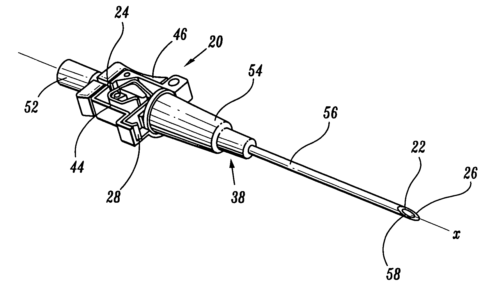
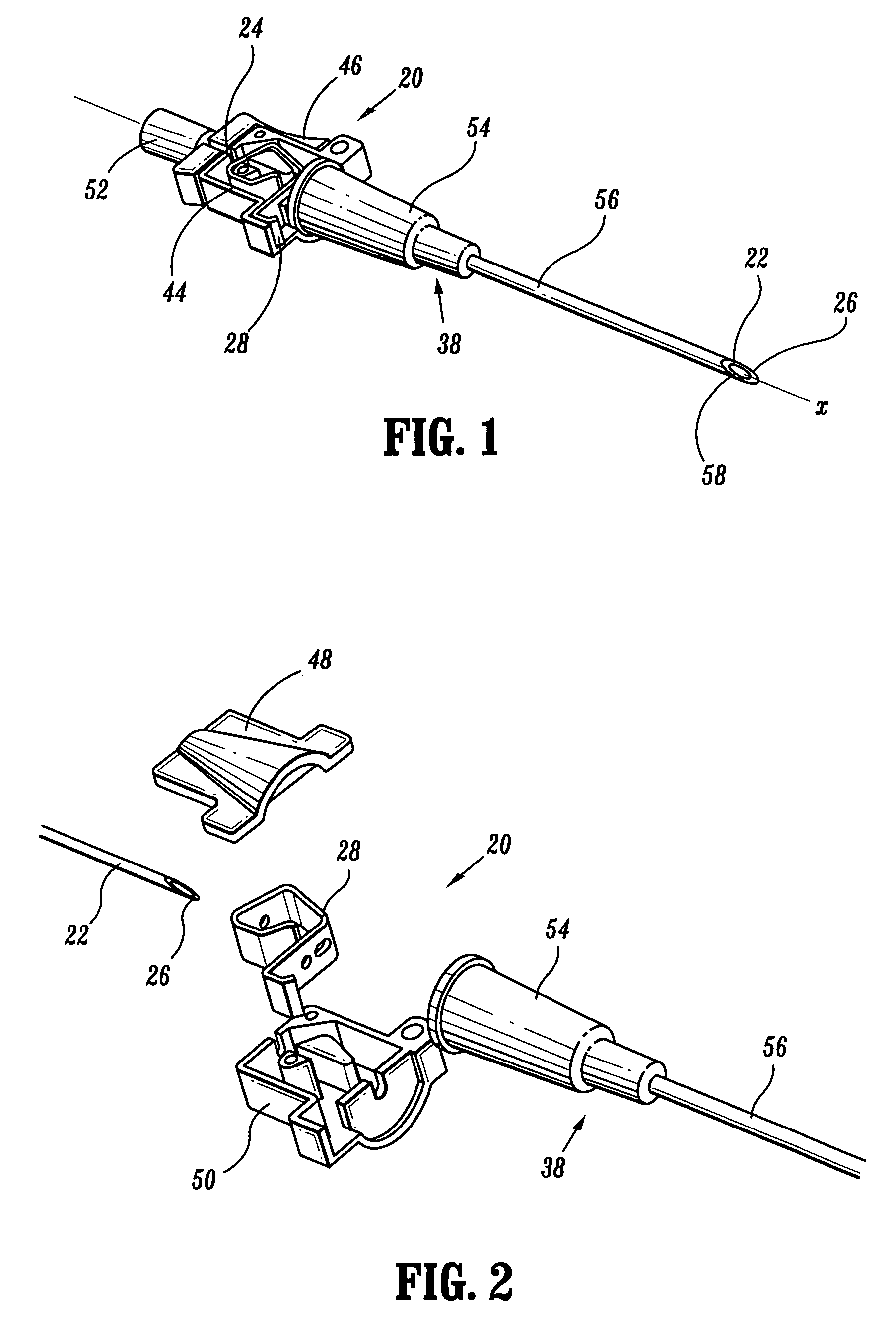
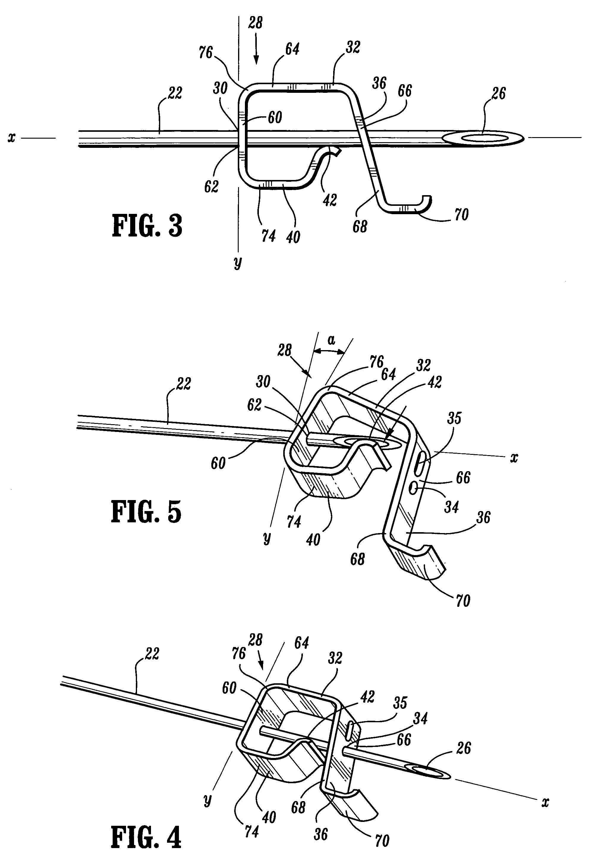
[0038]The exemplary embodiments of the safety shield and methods of operation disclosed are discussed in terms of medical piercing members such as, for example, hypodermic needles, biopsy needles, intravenous (IV) introducers, trocars, guide wires, thoracentesis needles, etc. for infusion of intravenous fluids, medication infusion or fluid sampling, and more particularly, in terms of a safety shield employed with a needle cannula that prevents hazardous exposure to a needle tip, including, for example, inadvertent needle sticks. It is envisioned that the present disclosure, however, finds application to a wide variety of cannula needles and devices for the infusion of preventive medications, medicaments, therapeutics, etc. to a subject. It is also envisioned that the present disclosure may be employed for collection of body fluids including those employed during procedures relating to phlebotomy, digestive, intestinal, urinary, veterinary, etc. It is contemplated that the safety shi...


PUM


Abstract

A safety shield including a protective device is provided including a piercing member having a proximal end, a distal end and defining a longitudinal axis. A clip defines a first cavity dimensioned for movement of the piercing member therethrough and is oriented in an axis transverse to the longitudinal axis. The first cavity is movable between a movable orientation and a binding orientation. The clip includes a first leg that defines a second cavity dimensioned for movement of the piercing member therethrough and a distal part being configured to engage a medical device. The clip further includes a second leg having a bearing surface that engages the piercing member. The legs are biased for convergent movement such that the first cavity is disposed in the binding orientation and the distal part of the first leg disengages the medical device.

Description

BACKGROUND[0001]1. Technical Field[0002]The present disclosure generally relates to the field of medical assemblies for the administration of fluids, and more particularly, to safety shields that prevent hazardous exposure to a medical piercing member.[0003]2. Description of the Related Art[0004]Problems associated with inadvertent sticks and punctures from traditional non-safety medical devices are well known in the art of fluid administration, which includes fluid sampling, percutaneous medication injection and other medical procedures involving the use of medical piercing members such as, for example, hypodermic needles, biopsy needles, intravenous (IV) introducers, trocars, guide wires, thoracentesis needles, etc. Significant attention is focused on health risks associated with hazardous needle exposure due to the contemporary sensitivity of exposure to AIDS, Hepatitis and other blood-borne pathogens. These risks are some of the most prevalent occupational health hazards among h...

Claims


Application Information

Patent Timeline
Patent Type & Authority Patents(United States)
IPC IPC(8): A61M5/178A61M5/00A61M5/32A61M25/06
CPCA61M5/3273A61M25/0618A61M5/326A61M2005/3249A61M2005/325
Inventor CARLYON, JAMESFISER, RICHARD L.TARTOCK, RUSSELL
Owner KPR U S LLC
Why Eureka
Try Eureka