Soft tissue anchors and implantation techniques

a soft tissue anchor and anchor technology, applied in the field of soft tissue anchors, can solve the problems of excess force applied to the anchor, failure elsewhere on the anchor, etc., and achieve the effects of reducing or eliminating the danger of unscrewing the anchor, breaking the anchor, or tearing the tissue, and reducing or eliminating the danger of increasing the tension

Inactive Publication Date: 2015-12-10
4TECH
View PDF2 Cites 81 Cited by
  • Summary
  • Abstract
  • Description
  • Claims
  • Application Information

AI Technical Summary

Benefits of technology

[0005]One result of these differing thicknesses, yield strengths, and/or axial stiffnesses is that if excessive tension is applied to the proximal head, such as by a flexible longitudinal member as described below, the helical tissue-coupling element generally elongates along the first axial portion before along the second axial portion. The first axial portion thus serves as a mechanical fuse. Providing the first axial portion effective reduces the force on the main part of the anchor which holds the anchor in place, thereby reducing or eliminating the danger of unscrewing the anchor, breaking the anchor, or tearing the tissue, both during the implantation procedure and thereafter during long-term implantation of the anchor. Alternatively or additionally, the physician may reduce or cease increasing the tension before the second axial portion elongates, thereby reducing the risk of the elongation causing damage to the tissue in which the second axial portion is implanted, and the risk that the tension will pull the anchor from the tissue. For some applications, the physician senses elongation of the first axial portion in real time while applying the tension, such as by using imaging and/or tactile feedback. The first axial portion may undergo plastic deformation when elongated. As a result, excess force applied to the anchor is absorbed by the first axial portion, instead of detaching the anchor from the tissue, or causing failure elsewhere on the anchor.
[000...

Problems solved by technology

As a result, excess force applied to the anchor is absorbed by the first axial portion,...

Method used


Image

  • Soft tissue anchors and implantation techniques
  • Soft tissue anchors and implantation techniques
  • Soft tissue anchors and implantation techniques

Examples


Embodiment Construction

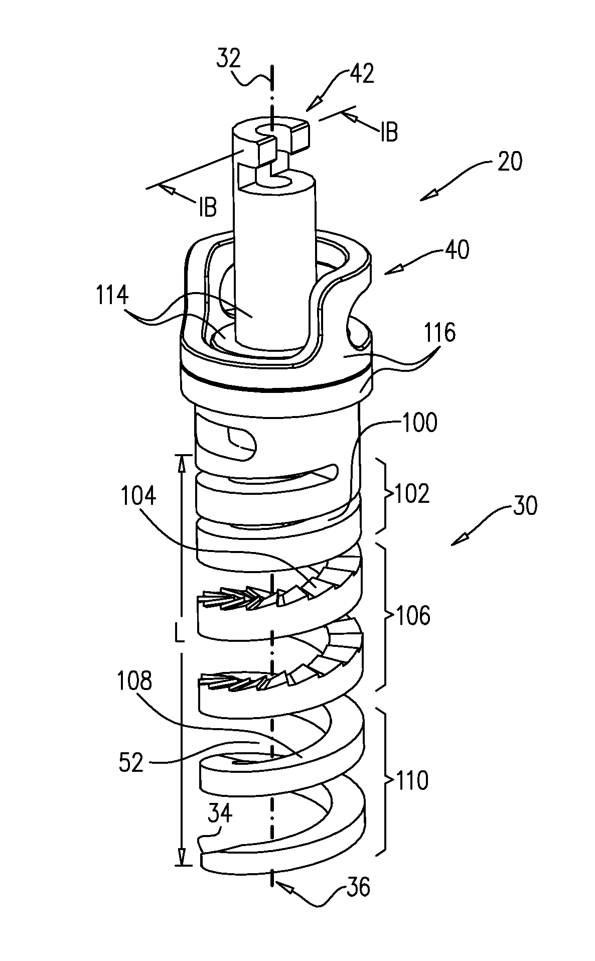
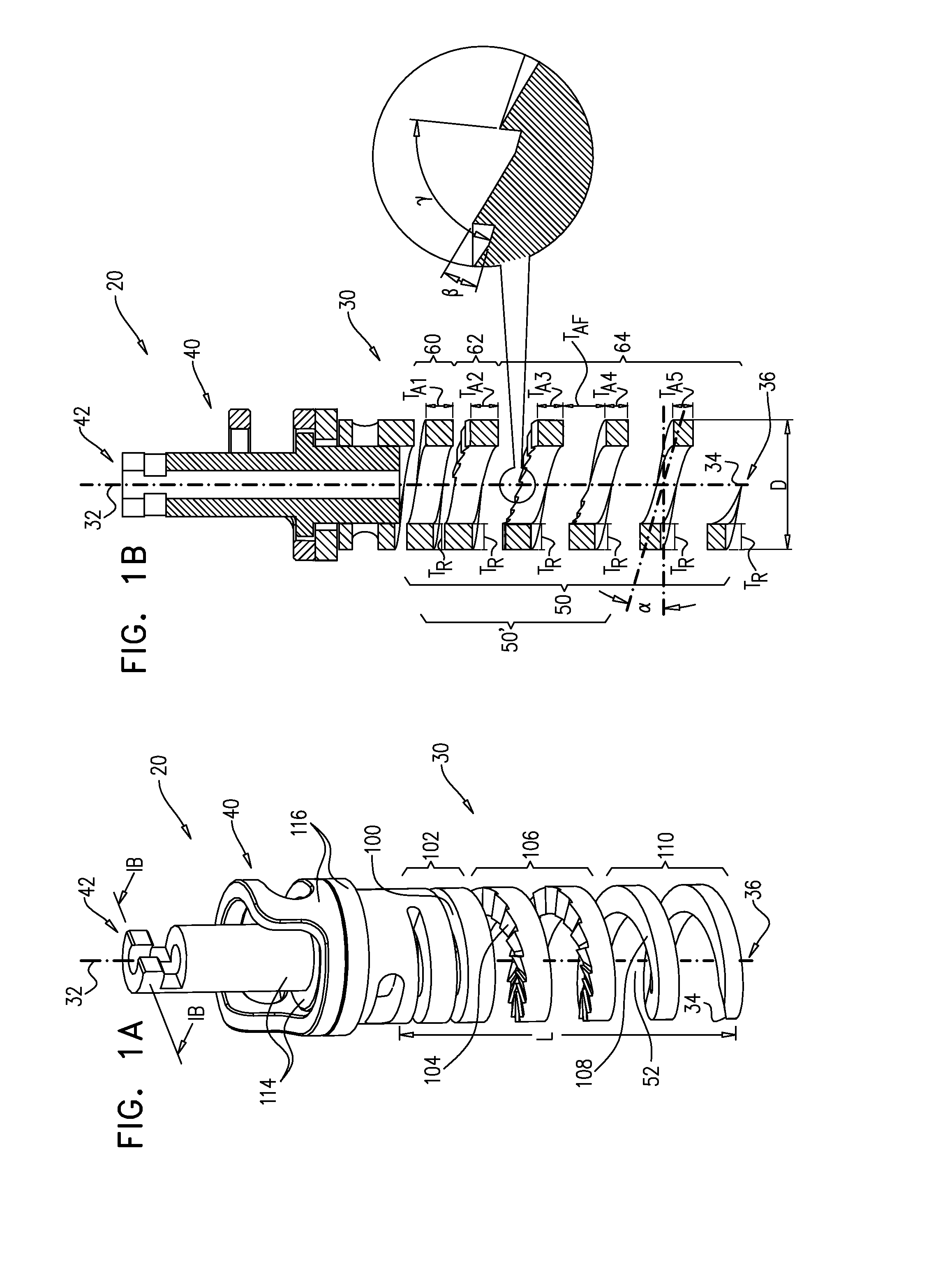
[0237]FIGS. 1A-B are schematic illustrations of a tissue anchor 20, in accordance with an application of the present invention. FIG. 1A is an isometric view of the anchor, and FIG. 1B is a cross-sectional view taken along line IB-IB of FIG. 1A. Tissue anchor 20 comprises a generally helical tissue-coupling element 30 disposed about a longitudinal axis 32 thereof and having a distal tissue-penetrating tip 34 at a distal end 36 of tissue anchor 20. Typically, tissue anchor 20 is shaped so as to define a head 40 at a proximal end 42 thereof. Typically, tissue-coupling element 30 has a generally rectangular, e.g., square, cross section.

[0238]For some applications, along at least a shaftless helical portion 50 of helical tissue-coupling element 30, an axial thickness TA of the helical tissue-coupling element varies while a radial thickness TR of the helical tissue-coupling element remains constant. Axial thickness TA is measured along axis 32, and radial thickness TR is measured perpendi...


PUM


Abstract

A tissue anchor (20) comprises a helical tissue-coupling element (30) disposed about a longitudinal axis (32) thereof and having a distal tissue-penetrating tip (34). The helical tissue-coupling element (30) has: a first axial stiffness along a first axial portion (60) of the helical tissue-coupling element (30); a second axial stiffness along a second axial portion (62) of the helical tissue-coupling element (30) more distal than the first axial portion (60), which second axial stiffness is greater than the first axial stiffness; and a third axial stiffness along a third axial portion (64) more distal than the second axial portion (62), which third axial stiffness is less than the second axial stiffness. Other embodiments are also described.

Description

CROSS-REFERENCE TO RELATED APPLICATIONS[0001]The present application is the US national stage of International Application PCT / IL2014 / 050027, filed Jan. 9, 2014, which claims priority from U.S. Provisional Application 61 / 750,427, filed Jan. 9, 2013, which is assigned to the assignee of the present application and is incorporated herein by reference.FIELD OF THE APPLICATION[0002]The present invention relates generally to tissue anchors, and specifically to anchors for tissue anchors for implantation in soft tissue, such as cardiac tissue.BACKGROUND OF THE APPLICATION[0003]Tissue anchors are used for anchoring elements, such as electrode leads or sutures, to tissue, such as bone or soft tissue. Some tissue anchors are shaped so as to define a shaft and screw thread therearound, while other tissue anchors are shaped so as define a helical tissue-coupling element without a shaft.SUMMARY OF THE APPLICATION[0004]Some applications of the present invention provide tissue anchors, each of wh...

Claims


Application Information

Patent Timeline
IPC IPC(8): A61F2/24
CPCA61F2/2478A61F2220/0016A61F2230/0091A61B17/06A61N1/0573A61B2017/0464A61B2017/06076A61B2017/0649A61B2017/0443A61B2090/062A61B17/0401A61F2/2487
Inventor GILMORE, MICHAELMURPHY, CHARLOTTETOBIS, IDAN
Owner 4TECH
Why Eureka
Try Eureka