Textile equipment cleaning device

A technology for cleaning devices and textile equipment, applied in the direction of electrostatic cleaning, cleaning methods and utensils, cleaning methods using gas flow, etc., can solve problems such as difficult cleaning, and achieve cleanliness, high recycling efficiency, and simple operation Effect

Inactive Publication Date: 2018-06-19
苏州朦井纺织科技有限公司
View PDF3 Cites 7 Cited by
  • Summary
  • Abstract
  • Description
  • Claims
  • Application Information

AI Technical Summary

Problems solved by technology

[0004] A textile equipment cleaning device proposed by the present invention solves the problem that it is not easy to clean because the thread end is pasted on the table of the textile equipment

Method used


Image

  • Textile equipment cleaning device
  • Textile equipment cleaning device
  • Textile equipment cleaning device

Examples


Embodiment 1

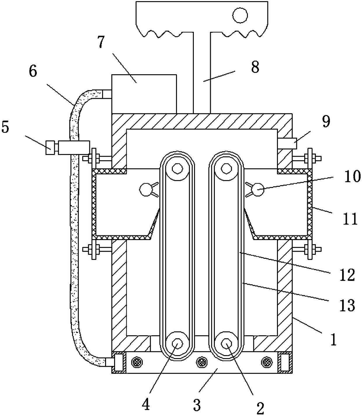
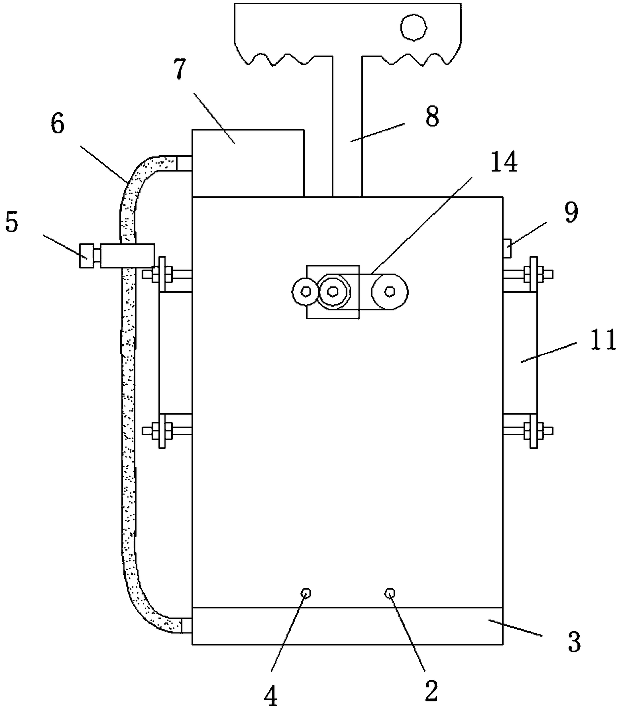
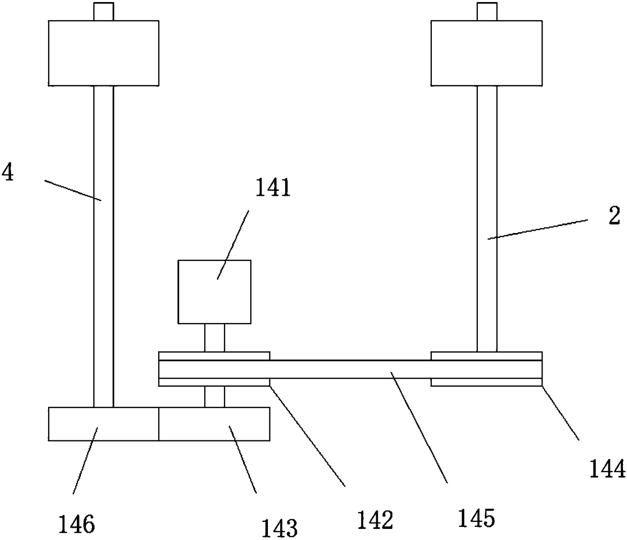
[0025] refer to figure 1 , 2 , 3, 4, 5, 6, a textile equipment cleaning device, comprising a housing 1, the housing 1 is a hollow cylinder, the bottom of the housing 1 is provided with a rectangular first through hole, the side of the housing 1 There are two sets of second through holes symmetrically arranged. The inside of the housing 1 and the first through hole at the bottom of the housing 1 are rotatably installed with a first rotating shaft 2 and a second rotating shaft 4, two first rotating shafts 2 and two Belt pulleys are installed on the second rotating shafts 4, belts 12 are connected between the two first rotating shafts 2 and between the two second rotating shafts 4, and electrostatic dust-absorbing cloths 13 are sewn on the outsides of the two sets of belts 12, A recovery device is installed in the second through hole, a driving device 14 is installed on the side of the housing 1, an exhaust pipe 9 is connected to the side of the housing 1, an air injection devic...

Embodiment 2

[0030] refer to figure 1 , 2 , 3, 5, 6, a textile equipment cleaning device, comprising a housing 1, the housing 1 is a hollow cylinder, the bottom of the housing 1 is provided with a rectangular first through hole, and the side of the housing 1 is provided with Two sets of symmetrically arranged second through holes, the inside of the housing 1 and the first through holes at the bottom of the housing 1 are rotatably installed with the first rotating shaft 2 and the second rotating shaft 4, two first rotating shafts 2 and two second rotating shafts Belt pulleys are installed on the two rotating shafts 4, and belts 12 are connected between the two first rotating shafts 2 and between the two second rotating shafts 4, and the outsides of the two groups of belts 12 are all sewn with electrostatic dust-absorbing cloths 13. A recovery device is installed in the through hole, a driving device 14 is installed on the side of the housing 1, an exhaust pipe 9 is connected to the side of...


PUM


Abstract

The invention relates to the technical field of textile equipment maintenance, in particular to a textile equipment cleaning device. According to the problem that a thread residue is attached to a table board of textile equipment and thus cannot be cleared easily in the prior art, the following solution is put forward. The textile equipment cleaning device comprises a shell which is a hollow cylinder. A rectangular first through hole is formed in the bottom of the shell. Two sets of second through holes are symmetrically formed in the side edge of the shell. First rotating shafts and second rotating shafts are both installed inside the shell and in the first through hole of the bottom of the shell in a rotating mode. Belt pulleys are both installed on the two first rotating shafts and thetwo second rotating shafts. Belts are both connected between the two first rotating shafts as well as between the two second rotating shafts. Electrostatic precipitation cloths are both sewn to the outsides of the two sets of the belts. Recovery devices are installed in the second through holes. A driving device is installed on the side edge of the shell. The side edge of the shell communicates with an exhaust pipe. An air injection device is installed at the top of the shell. The textile equipment cleaning device is easy to operate, cleanliness of the table board of the textile equipment is guaranteed, and the recovery efficiency is high.

Description

technical field [0001] The invention relates to the technical field of textile equipment maintenance, in particular to a textile equipment cleaning device. Background technique [0002] Textile equipment is all kinds of equipment needed to process natural fibers or chemical fibers into textiles. Although the equipment for producing chemical fibers includes a variety of chemical equipment, it is now considered an extension of textile equipment and belongs to textile equipment in a broad sense. The processes required to process different fibers such as cotton, hemp, silk, wool, etc. into textiles are not the same, and some are completely different, so the machines required are also various and varied. [0003] During the production process of textile equipment, there must be lint or thread ends left on the table. Some thread ends are easy to stick to the table and become very difficult to remove. Maintenance personnel need to manually remove them. The workload of the work is ...

Claims


Application Information

Patent Timeline
Patent Type & Authority Applications(China)
IPC IPC(8): B08B6/00B08B5/02
CPCB08B6/00B08B5/02
Inventor 计振南
Owner 苏州朦井纺织科技有限公司
Why Eureka
Try Eureka