Bed changing device for critical patient

A patient and critically ill technology, applied in the field of bed changing devices for critically ill patients, can solve the problems of high labor intensity, patient discomfort, secondary injury, etc.

Inactive Publication Date: 2018-06-22
张明明 +3
View PDF5 Cites 2 Cited by
  • Summary
  • Abstract
  • Description
  • Claims
  • Application Information

AI Technical Summary

Problems solved by technology

[0002] For patients, due to examination or other needs during hospitalization, it is necessary to change the bed for examination or care. However, since patients are often unable to move by themselves, especially critically ill patients or patients with fractures in the ICU, they need to transfer beds In the process, it often requires the synergy of 4-6 medical workers or family members at the same time to barely l...

Method used


Image

  • Bed changing device for critical patient
  • Bed changing device for critical patient
  • Bed changing device for critical patient

Examples


Embodiment 1

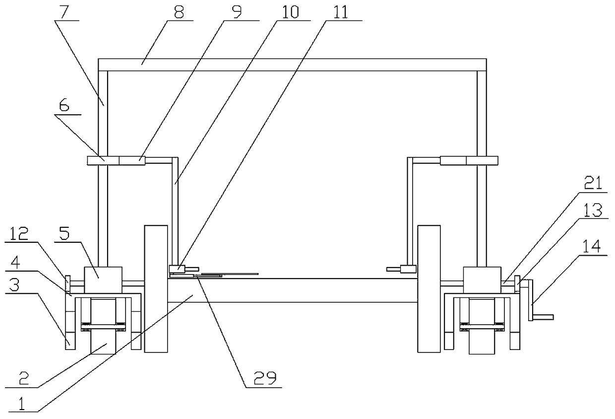
[0046] Embodiment one, a bed changing device for critically ill patients, comprising a supporting mechanism, a walking mechanism provided on the supporting mechanism, a lifting mechanism provided on the walking mechanism, a lifting mechanism provided on the lifting mechanism, An auxiliary support mechanism 29 provided at the lower part of the lifting mechanism, a drive mechanism provided on the support mechanism and matched with the walking mechanism, and a control provided on the drive mechanism for controlling the operation of the lifting mechanism mechanism;

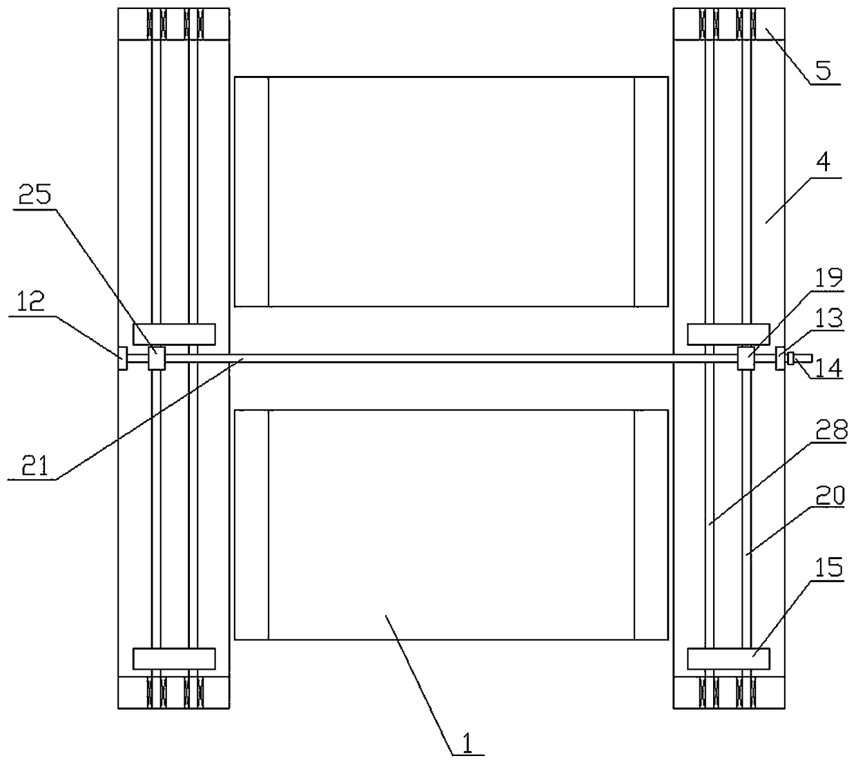
[0047] The supporting mechanism includes two supporting plates 4 that cooperate with each other, a plurality of supporting bosses 3 arranged on the lower end of the supporting plate 4, and a plurality of supporting bosses 3 arranged on the supporting plate 4 and matched with the plurality of supporting bosses 3. The traveling module is an auxiliary vertical board 5 arranged at both ends of the supporting board 4 and matc...

Embodiment 2

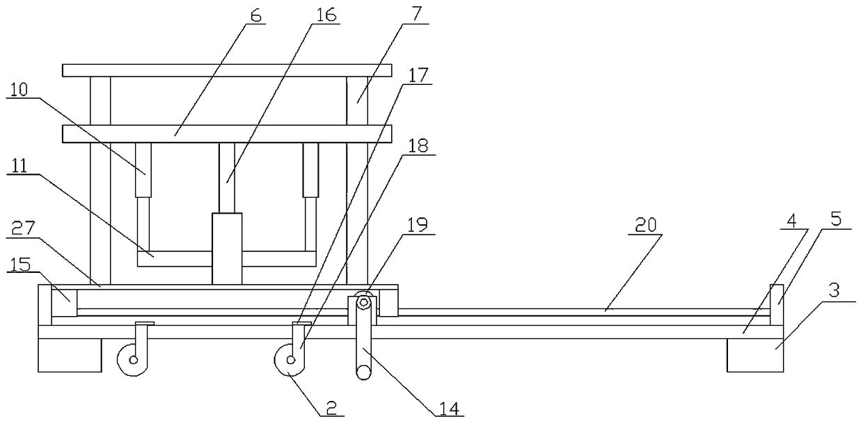
[0065] The difference from the first embodiment is that the bridge rod 21 is a quadrangular prism.

[0066] Because the reinforced crossbar in this embodiment only bears the pressure at both ends, it is composed of multiple-section reinforced bars. In this way, it is ensured to adapt to beds of different lengths; in this embodiment, the driving support frame and the driven support frame are both arranged at the two ends of the support plate.

Embodiment 3

[0068] The difference from the second embodiment is that the number of the walking platforms 15 is four, and they are all set close to the two ends of the walking board.

[0069] In this embodiment, four walking platforms are provided, which can enhance the structural strength and ensure the supporting effect. At the same time, to ensure the supporting effect, ribs can be provided on the lower or upper surface of the walking board to ensure the strength of the structure.


PUM


Abstract

The invention provides a bed changing device for a critical patient. The bed changing device comprises a supporting mechanism, a walking mechanism, a lifting mechanism, a hoisting mechanism, an auxiliary supporting mechanism, a driving mechanism and a control mechanism. The walking mechanism is arranged on the supporting mechanism; the lifting mechanism is arranged on the walking mechanism; the hoisting mechanism is arranged on the lifting mechanism; the auxiliary supporting mechanism is arranged on the lower portion of the hoisting mechanism; the driving mechanism is arranged on the supporting mechanism and matched with the walking mechanism; the control mechanism is arranged on the driving mechanism and used for controlling operation of the lifting mechanism. In application of the bed changing device, bedding can be fixed and tightened directly; the patient laying on the bedding can be lifted together with the bedding by the lifting mechanism while the limbs of the patient can be supported; the patient is then moved to a hospital bed through the walking mechanism; thus, labor intensity of medical staff in moving the patient to the other hospital bed is lowered, and uncomfortablefeelings of the patient caused by improper force from the medical staff and imperfect cooperation between the patient and the medical staff during transferring is also reduced.

Description

Technical field [0001] The invention belongs to the technical field of medical equipment, and specifically relates to a bed changing device for critically ill patients. Background technique [0002] For patients, during hospitalization, due to examination or other needs, they need to change their beds for examination or care. However, because patients are often unable to move themselves, especially severe patients or fracture patients in the ICU, they are transferring beds. In the process, it often takes 4-6 medical workers or family members to work together at the same time to barely hold the patient up and transfer to other beds. This process is not only labor-intensive, but also requires good cooperation. Insufficient strength or insufficient coordination will cause the patient’s posture to change to one side, causing discomfort or even secondary injury to the patient. Therefore, a way to coordinate the operation by 1-2 people is required, and then the operation The mechanica...

Claims


Application Information

Patent Timeline
IPC IPC(8): A61G7/14
CPCA61G7/1019A61G7/1025A61G7/1046A61G7/1057A61G7/1063A61G7/1073A61G2203/10A61G2203/70
Inventor 张桂华
Owner 张明明
Why Eureka
Try Eureka