Test tube rack

A test tube rack and test tube technology, which is applied in the directions of test tube racks/clamps, laboratory utensils, etc., can solve the problems of inconvenient use of test tube racks, and achieve the effect of convenient use.

Inactive Publication Date: 2018-06-22
陈常怡 +2
View PDF6 Cites 0 Cited by
  • Summary
  • Abstract
  • Description
  • Claims
  • Application Information

AI Technical Summary

Problems solved by technology

[0003] Aiming at the deficiencies of the prior art, the present invention provides a test tube rack, which is used to solve the problem of inconvenient use of the test tube rack in the prior art

Method used


Image

  • Test tube rack
  • Test tube rack

Examples


Embodiment 1

[0032] The first embodiment provides a test tube rack.

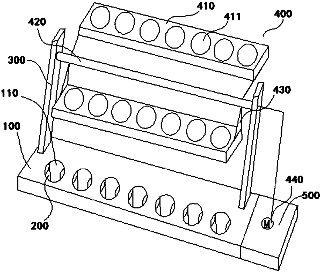
[0033] Please refer to figure 1 , the test tube rack includes a base 100 and a first stopper 200 .

[0034] Wherein, the base 100 is provided with a test tube hole 110 . The first limiting member 200 has elasticity, and the first limiting member 200 is arranged in the test tube hole 110. When different types of test tubes are inserted into the test tube hole 110, the first limiting member 200 can be used according to the size of the different types of test tubes. Realize the limit of the test tube.

[0035] In this way, since the elastic first stopper 200 is arranged in the test tube hole 110 on the base 100, when different types of test tubes are inserted into the test tube hole 110, the first stopper 200 can be adjusted according to the size of the test tube. Adjust to realize the limit of the test tube. Specifically, during the insertion process of the test tube, the outer wall of the test tube will squeeze the fir...

Embodiment 2

[0060] The second embodiment also provides a test tube rack.

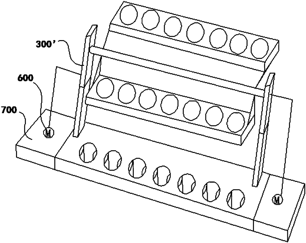
[0061] Please refer to figure 2 , the test tube rack includes a base 100, a first limiting member 200, a limiting component 400 and the like. The base 100 , the first limiting member 200 and the limiting component 400 are described in detail in the first embodiment, and will not be repeated here.

[0062] Different from the first embodiment, the support rod in the second embodiment adopts a telescopic telescopic rod 300'.

[0063] In this way, after the stop assembly 400 is installed on the telescopic rod 300', the vertical height between the second stop member 410 and the base 100 can be adjusted by adjusting the expansion and contraction of the telescopic rod 300', so as to further improve the stop of the test tube Effect.

[0064] Wherein, the above-mentioned telescopic rod 300' can adopt any kind of telescopic rod, and it can be realized by multiple ways such as air cylinder and hydraulic cylinder.

[0065...


PUM


Abstract

The invention discloses a test tube rack, which comprises a base and a first position limiting element, wherein a test tube hole is formed in the base; the first position limiting element has elasticity; the first position limiting element is arranged in the test tube hole; when test tubes of different models are inserted into the test tube holes, the first position limiting element can realize the position limitation on the test tube according to the dimension of the test tubes of different models. The test tube rack can meet the use requirements of the test tubes of different models, so thatthe use convenience of a user is greatly improved.

Description

technical field [0001] The invention relates to the technical field of medical equipment, in particular to a test tube rack. Background technique [0002] Test tubes and test tube racks are often used in medical experiments. Existing test tube racks are usually set up with test tubes, that is, one type of test tube uses one type of test tube rack, and the test tube rack cannot meet the use of test tubes of different types or sizes. For example, various test tubes of different types are usually used in medical experiments, and they are respectively placed on different test tube racks, which not only occupies a lot of space on the test bench, but also is inconvenient for test personnel to take and place. For this reason, the common method that adopts in the prior art is to arrange the test tube holes of multiple different sizes on the same test tube rack, to adapt to the placement of different types of test tubes, but in the actual operation process, it is necessary to place t...

Claims


Application Information

Patent Timeline
IPC IPC(8): B01L9/06
CPCB01L9/06B01L2200/023
Inventor 陈常怡肖庆罗颖
Owner 陈常怡
Why Eureka
Try Eureka