Leather hose cutting machine for fire-fighting equipment production
A fire-fighting equipment and cutting machine technology, applied in metal processing and other directions, can solve the problems of easily injured operators and low cutting efficiency.
- Summary
- Abstract
- Description
- Claims
- Application Information
AI Technical Summary
Problems solved by technology
Method used
Image

Examples
Embodiment 1
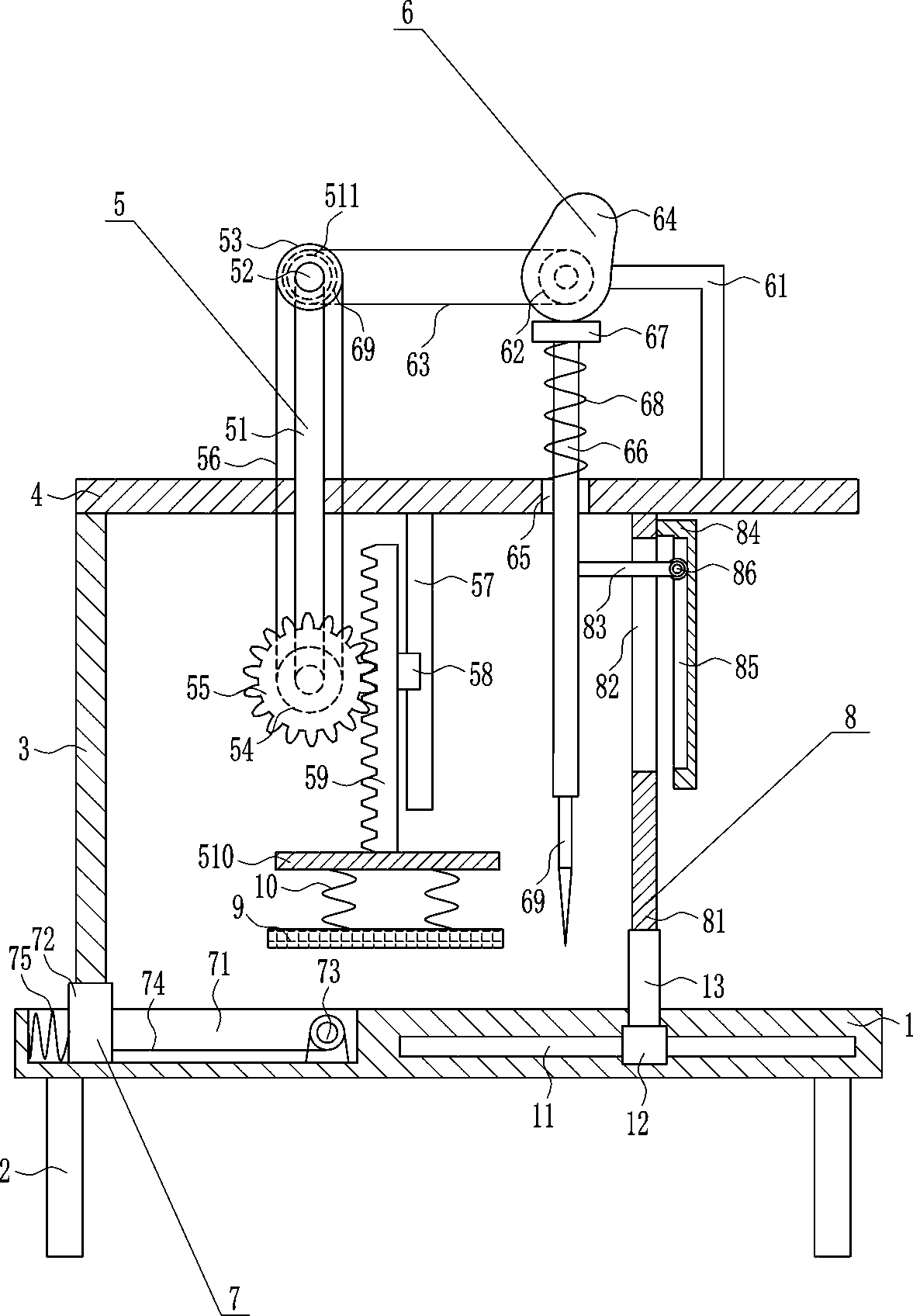
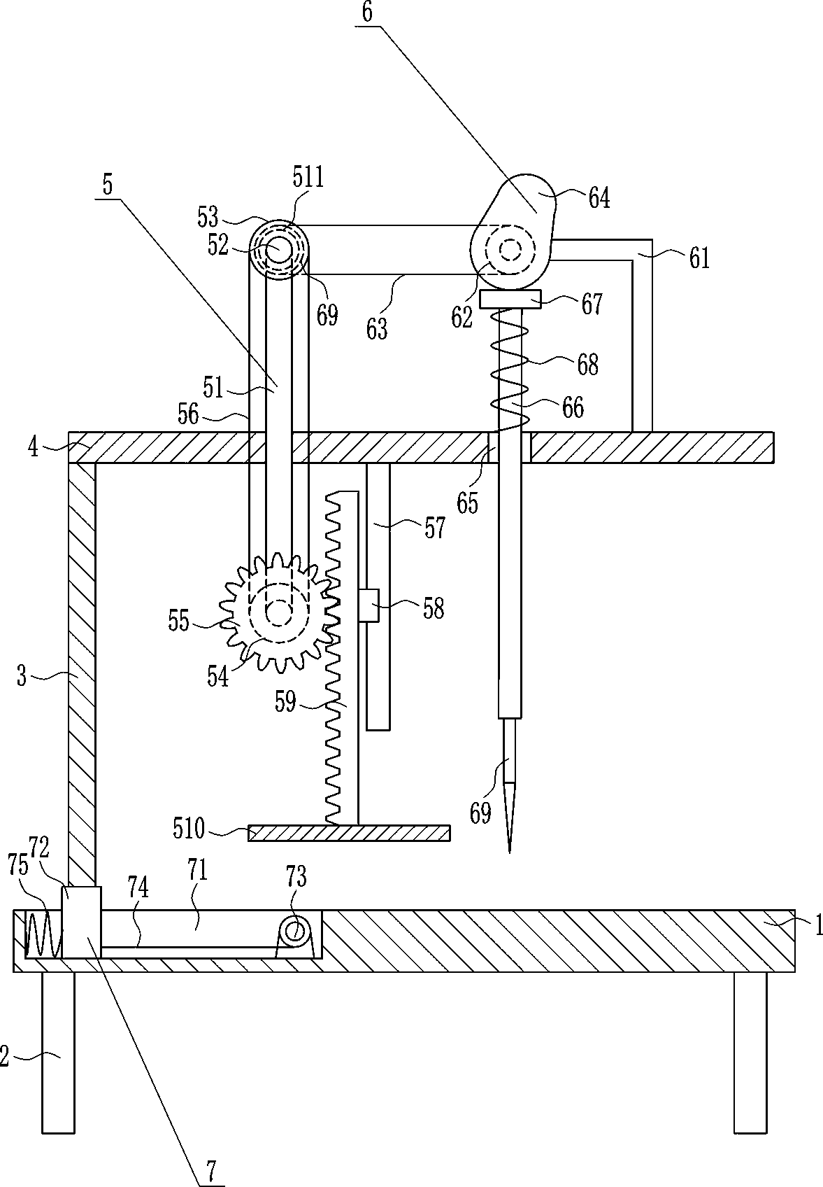
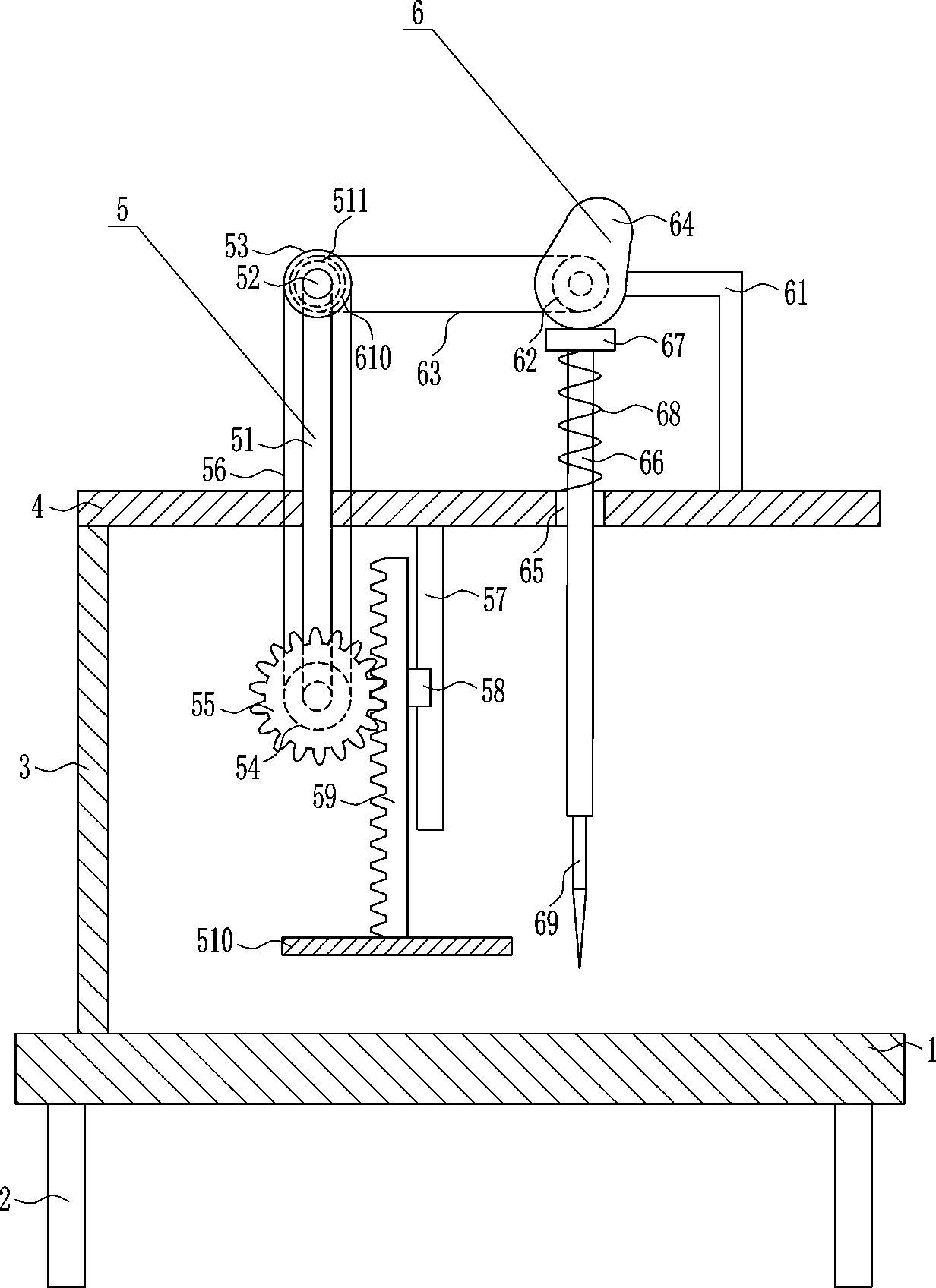
[0031] A leather tube cutting machine for fire fighting equipment production, such as Figure 1-5 As shown, it includes a bottom plate 1, legs 2, support plate 3, top plate 4, pressing device 5 and cutting device 6, legs 2 are installed at the four corners of the bottom of the bottom plate 1, and a support plate 3 is installed on the top left of the bottom plate 1 , a top plate 4 is installed horizontally on the top of the support plate 3, a pressing device 5 is provided on the front side of the top plate 4, a cutting device 6 is arranged on the right side of the top plate 4, and the cutting device 6 is located on the right side of the pressing device 5, and the cutting device 6 cuts Components are located above base plate 1.
Embodiment 2
[0033] A leather tube cutting machine for fire fighting equipment production, such as Figure 1-5 As shown, it includes a bottom plate 1, legs 2, support plate 3, top plate 4, pressing device 5 and cutting device 6, legs 2 are installed at the four corners of the bottom of the bottom plate 1, and a support plate 3 is installed on the top left of the bottom plate 1 , a top plate 4 is installed horizontally on the top of the support plate 3, a pressing device 5 is provided on the front side of the top plate 4, a cutting device 6 is arranged on the right side of the top plate 4, and the cutting device 6 is located on the right side of the pressing device 5, and the cutting device 6 cuts Components are located above base plate 1.
[0034] The pressing device 5 includes a first mounting rod 51, a first rotating shaft 52, a first pulley 53, a second pulley 54, a gear 55, a first flat belt 56, a first slide rail 57, a first slide block 58, a rack 59. The pressing plate 510 and the f...
Embodiment 3
[0036] A leather tube cutting machine for fire fighting equipment production, such as Figure 1-5 As shown, it includes a bottom plate 1, legs 2, support plate 3, top plate 4, pressing device 5 and cutting device 6, legs 2 are installed at the four corners of the bottom of the bottom plate 1, and a support plate 3 is installed on the top left of the bottom plate 1 , a top plate 4 is installed horizontally on the top of the support plate 3, a pressing device 5 is provided on the front side of the top plate 4, a cutting device 6 is arranged on the right side of the top plate 4, and the cutting device 6 is located on the right side of the pressing device 5, and the cutting device 6 cuts Components are located above base plate 1.
[0037] The pressing device 5 includes a first mounting rod 51, a first rotating shaft 52, a first pulley 53, a second pulley 54, a gear 55, a first flat belt 56, a first slide rail 57, a first slide block 58, a rack 59. The pressing plate 510 and the f...
PUM
 Abstract
Description
Claims
Application Information
 - R&D
- Intellectual Property
- Life Sciences
- Materials
- Tech Scout
- Unparalleled Data Quality
- Higher Quality Content
- 60% Fewer Hallucinations
Browse by: Latest US Patents, China's latest patents, Technical Efficacy Thesaurus, Application Domain, Technology Topic, Popular Technical Reports.
© 2025 PatSnap. All rights reserved.Legal|Privacy policy|Modern Slavery Act Transparency Statement|Sitemap|About US| Contact US: help@patsnap.com