Material delivery mechanism for injection molding machine

A conveying mechanism and injection molding machine technology, applied in the field of injection molding machines, can solve the problems of time-consuming, product performance degradation, high labor intensity, etc., and achieve the effects of simple and smart mechanism, consistent product performance, and smart and convenient structure

Pending Publication Date: 2018-06-22
HAITIAN PLASTICS MACHINERY GRP
View PDF5 Cites 2 Cited by
  • Summary
  • Abstract
  • Description
  • Claims
  • Application Information

AI Technical Summary

Problems solved by technology

[0003] The disadvantages of using cylinder direct pressure to force conveying are: ⑴The sealing effect is poor, and the problem of material leakage is prominent
The direct pressure of the oil cylinder is used for forced conveying, which requires a high sealing effect between the feeding head and the material cylinder. For materials that are solid and blocky, the material is easy to leak from the pressure head and the material cylinder. Adhesion solidifies on the feeding head, causing damage to the sealing ring and exacerbating material leakage
⑵Serious shearing of materials, uneven composition, and obvious decline in product performance
The direct pressure of the oil cylinder is used for forced transportation, and the liquid resin in the block material is easily precipitated under pressure, which makes the composition of the molded product uneven and the performance is unstable; at the same time, the material is squeezed and sheared by the high-strength plunger, and the mechanical properties of the material drop sharply. , leading to a significant drop in the performance parameters of the final product in all aspects
(3) Complex and huge mechanism, inconvenient operation and maintenance, high labor intensity and poor practicability
The original mechanism is limited by the structural size of the oil cylinder, the overall mechanism is relatively large, and is limited by the amount of feeding. The feeding port can only be located above the overall mechanism. The operator can only use an additional feeding platform to perform operations such as feeding and maintenance, which is time-consuming. , laborious, reducing the safety and convenience of the operation, and the practicability is poor

Method used


Image

  • Material delivery mechanism for injection molding machine
  • Material delivery mechanism for injection molding machine
  • Material delivery mechanism for injection molding machine

Examples


Embodiment Construction

[0030] The specific implementation manners of the present invention will be further described below in conjunction with the accompanying drawings, so as to make the technical solution of the present invention easier to understand and grasp.

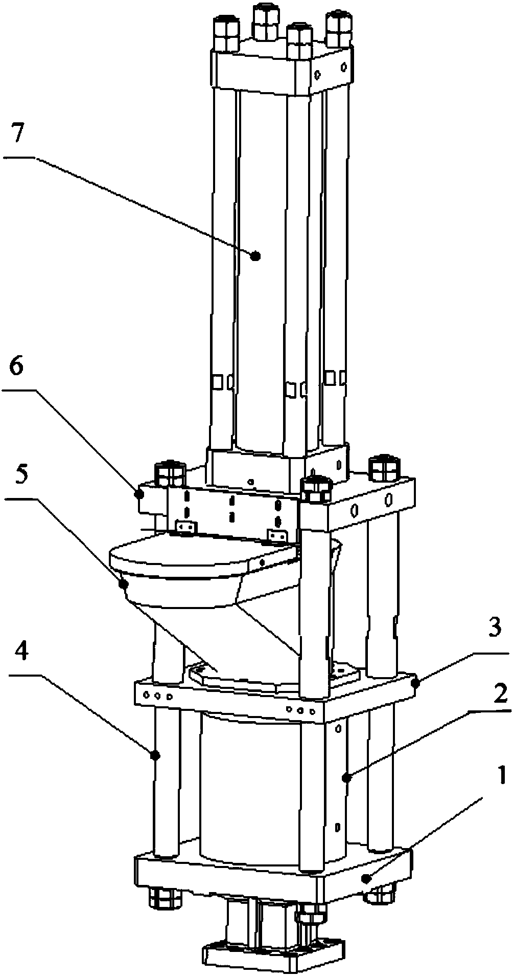
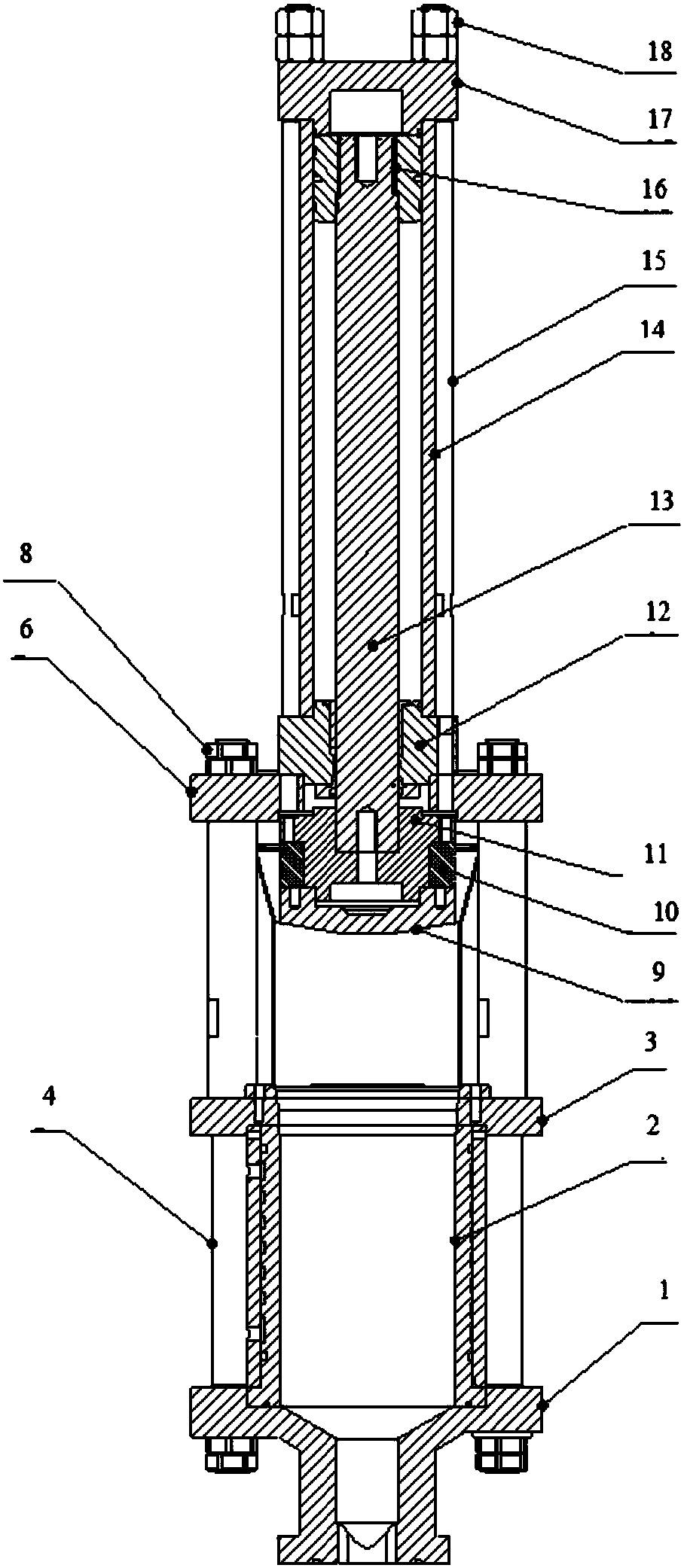
[0031] Such as Figure 1 to Figure 2 As shown, the traditional block material feeding mechanism of injection molding machine includes a lower frame composed of a feeding base 1, a feeding bottom plate 3, a cylinder support 6 and a first pull rod 4, and a cylinder support 6, a cylinder top seat 12 and a second pull rod 15. Composed of the upper frame, the feeding cylinder 2 is arranged between the feeding base plate 3 and the feeding base 1, and the feeding funnel 5 is arranged between the feeding base plate 3 and the cylinder bracket 6, and the feeding cylinder 2 and the feeding funnel 5 pass through the first pull rod 4 and are located on the cylinder bracket The first nut 8 on the upper end surface of 6 is connected, and the feeding cyl...


PUM


Abstract

The invention discloses a material delivery mechanism for an injection molding machine. The material delivery mechanism includes a material feeding box and a material feeding cylinder which are successively connected, and a delivery screw rod which penetrates through the material feeding box and the material feeding cylinder; the delivery screw rod includes a rod body and a rod head, wherein the rod head is arranged inside the material feeding cylinder and the rod body is located in the material feeding box; an end of the rod body is stretched out from the material feeding box and is connectedto a driving unit which drives the delivery screw rod to rotate; screw ribs are formed on the surface of the delivery screw rod, wherein the screw ribs on the rod body are partly milled to form milled notches. The material delivery mechanism has excellent sealability, can stir and mix materials uniformly, has simplified structure, and is convenient to install, operate and maintain.

Description

technical field [0001] The invention relates to the field of injection molding machines, more specifically, it relates to a material conveying mechanism of an injection molding machine. Background technique [0002] For the transportation of bulk materials in injection molding machines, due to the coagulation characteristics of the bulk materials themselves, if you want to achieve the effect of dense and uniform material quality during the transportation process, you need to apply external force to make the raw materials compact and then convey. Existing injection molding machines The bulk material conveying generally adopts the cylinder push and direct pressure mode. [0003] The disadvantages of using cylinder direct pressure to force conveying are: (1) The sealing effect is poor, and the problem of material leakage is prominent. The direct pressure of the oil cylinder is used for forced conveying, which requires a high sealing effect between the feeding head and the mate...

Claims


Application Information

Patent Timeline
Patent Type & Authority Applications(China)
IPC IPC(8): B29C45/18
CPCB29C45/18B29C2045/1875
Inventor 叶群方张龙启顾建华罗杰董升杨朝富
Owner HAITIAN PLASTICS MACHINERY GRP
Why Eureka
Try Eureka