Pressure relief device

A pressure relief device and pressure rod technology, applied in valve devices, safety valves, engine components, etc., can solve the problems of system shutdown, shutdown loss, rupture disc or valve failure, etc., to reduce the impact of friction and work. The effect of a good environment and low downtime costs

Active Publication Date: 2018-06-22
SHANGHAI QIYAO THERMAL ENERGY ENG CO LTD +1
View PDF6 Cites 2 Cited by
  • Summary
  • Abstract
  • Description
  • Claims
  • Application Information

AI Technical Summary

Problems solved by technology

[0002] At present, the safety pressure relief devices commonly used in the market include burst discs and spring safety valves. These pressure relief devices are cheap and widely used, but they generally have the following disadvantages: 1. Low efficiency, time-consuming installation and maintenance; 2. Poor accuracy, Usually the control accuracy is above ±10%; 3. It is inconvenient to replace and replace. When replacing parts, the system needs to stop working, resulting in downtime losses; 4. Poor fatigue resistance. Due to the lack of fatigue resistance, bursting discs or valves often fail. unable to work properly
Due to the above shortcomings, these safety pressure relief devices cannot meet the needs of the market well

Method used


Image

  • Pressure relief device
  • Pressure relief device
  • Pressure relief device

Examples


Embodiment Construction

[0050] In the following description, numerous specific details are given in order to provide a more thorough understanding of the present invention. It will be apparent, however, to one skilled in the art that the present invention may be practiced without one or more of these details. In other examples, some technical features known in the art are not described in order to avoid confusion with the present invention.

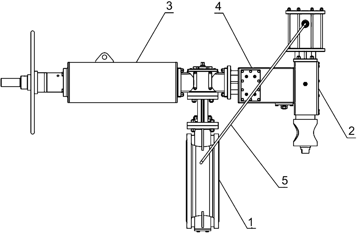
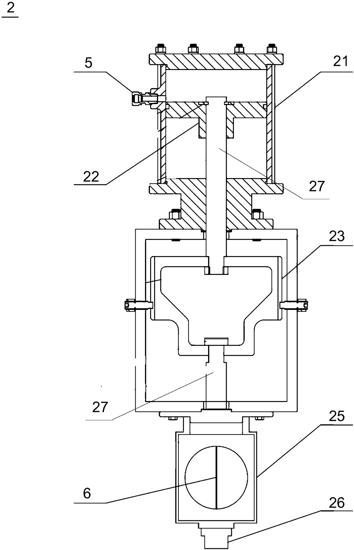
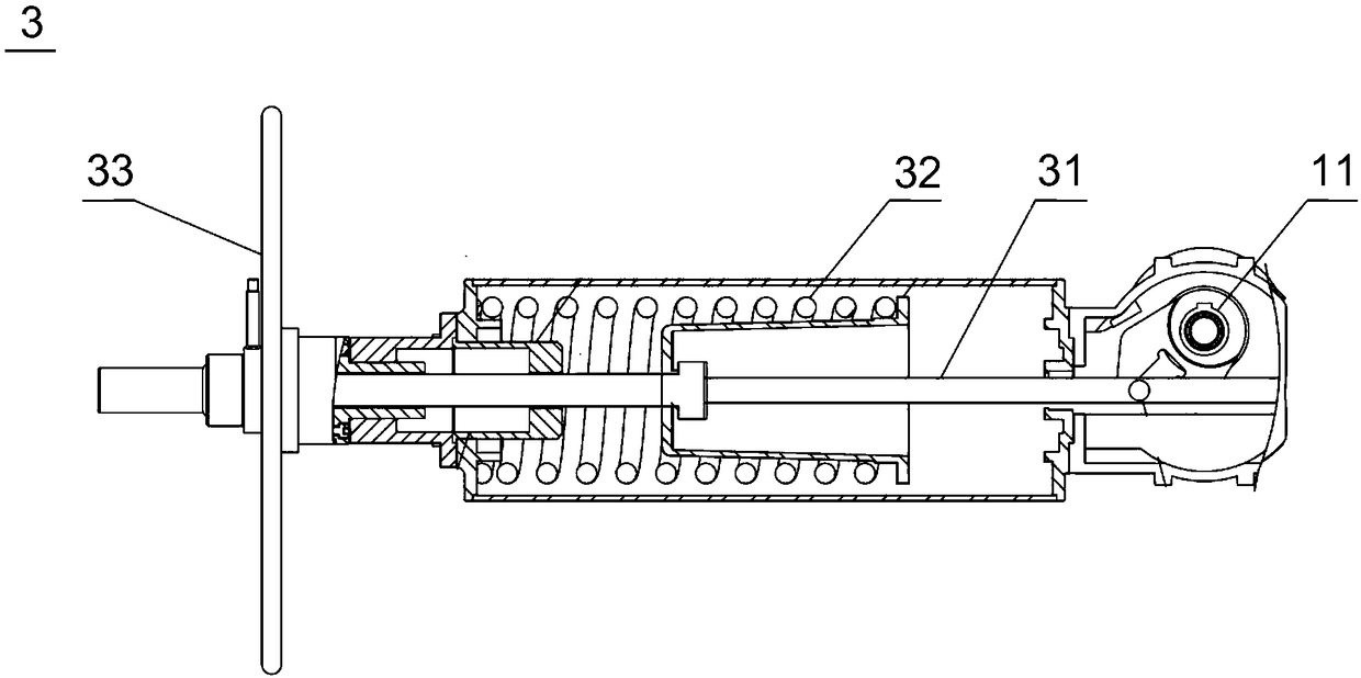
[0051] The invention provides a pressure relief device, which can be used for overpressure protection of pressure-bearing equipment, and can release pressure safely when the pressure inside the pressure-bearing equipment exceeds a set pressure value. Such as figure 1 As shown, the pressure relief device mainly includes a sealing valve 1, a valve stem mechanism 2, a power mechanism 3, a pressure lever mechanism 4, a pressure-taking pipeline 5 and a blasting needle 6 ( figure 1 not shown).

[0052] The sealing valve 1 includes a valve body for sealing and closi...


PUM


Abstract

The invention provides a pressure relief device. The pressure relief device comprises a sealing valve, a blasting needle, a valve rod mechanism, a power mechanism and a compression bar mechanism; thevalve rod mechanism bears the pressure of the inlet end of the sealing valve and axially extrudes the blasting needle; the power mechanism is connected to the sealing valve and has a tendency to openthe sealing valve; when the blasting needle is stable, the valve rod mechanism is not triggered, levers of the compression bar mechanism are limited, the levers limit baffles so as to lock the power mechanism in a state that the sealing valve is closed; when the pressure exceeds a set pressure value, the blasting needle is unstable, when the valve rod mechanism is triggered, the levers do not limit the baffles, so that the levers lose the limiting effect on the power mechanism, and the power mechanism drives the sealing valve to be opened for pressure relief. According to the pressure relief device, the pressure relief precision is high, debris is not generated in the pressure relief process, the maintenance cost is avoided, reset is simple, and the shutdown cost is low; and in addition, the levers and the baffles are coordinated with the action of a control lever, so that the influence of the friction force can be reduced, and therefore the pressure relief device can be more sensitivein response.

Description

technical field [0001] The present invention generally relates to a pressure relief device for overpressure protection of pressure equipment. Background technique [0002] At present, the safety pressure relief devices commonly used in the market include burst discs and spring safety valves. These pressure relief devices are cheap and widely used, but they generally have the following disadvantages: 1. Low efficiency, time-consuming installation and maintenance; 2. Poor accuracy, Usually the control accuracy is above ±10%; 3. It is inconvenient to replace and replace. When replacing parts, the system needs to stop working, resulting in downtime losses; 4. Poor fatigue resistance. Due to the lack of fatigue resistance, bursting discs or valves often fail. unable to work properly. Due to the above disadvantages, these safety pressure relief devices cannot well meet the needs of the market. [0003] Therefore, there is a need for a pressure relief device that at least partial...

Claims


Application Information

Patent Timeline
Patent Type & Authority Applications(China)
IPC IPC(8): F16K17/02F16K37/00
CPCF16K17/02F16K37/00
Inventor 刘世俊甘泉侯守坤许祥禄张磊
Owner SHANGHAI QIYAO THERMAL ENERGY ENG CO LTD
Why Eureka
Try Eureka