
Diaphragm cylinder device

A technology of cylinder device and diaphragm, which is applied in the direction of fluid pressure actuating device, etc., can solve the problems of pump device discharge accuracy drop, linearity drop, diaphragm 7 aging, etc., and achieve the effect of improving action characteristics and ensuring linearity

Inactive Publication Date: 2009-09-30
SANKYO SEIKI MFG CO LTD
View PDF12 Cites 1 Cited by
  • Summary
  • Abstract
  • Description
  • Claims
  • Application Information

AI Technical Summary

Problems solved by technology

[0008] In the diaphragm cylinder device constituted in this way, when the fluid flows in or out in the chamber 80 or when the piston 6 is driven, the outer peripheral side annular portion 72 and the inner peripheral side annular portion 74 are also deformed, and the inner portion of the chamber 80 is deformed. The linearity between the volume and the position of the piston 6 decreases, and there is a problem that the operating characteristics of the actuator and the operating characteristics of the pump device are reduced.
In addition, if the diaphragm 7 deforms unnaturally, there will be a problem that the diaphragm 7 will age in a short time.
[0009] In particular, when a diaphragm cylinder device is used as a pump device, if the piston 6 is displaced toward the bottom dead center, the chamber 80 becomes negative pressure. Figure 5 As shown by the dotted line in (b), the outer circumferential side annular portion 72 and / or the inner circumferential side annular portion 74 are sometimes deformed due to the negative pressure in the chamber 80. Once this happens, the chamber 80 The linearity between the internal volume of the pump and the position of the piston 6 will be destroyed, and there will be problems such as a decrease in the discharge accuracy of the pump device.

Method used


Image

  • Diaphragm cylinder device
  • Diaphragm cylinder device
  • Diaphragm cylinder device

Examples


Embodiment approach 1

[0059] (the whole frame)

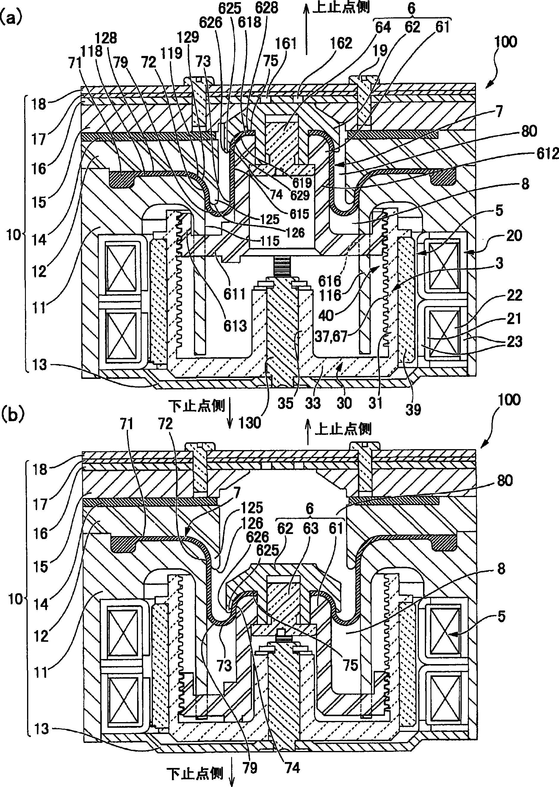
[0060] figure 1 (a), (b) are longitudinal sectional views of the diaphragm pump device to which the present invention is applied, figure 1 (a) shows the state of the piston at the top dead center, figure 1 (b) shows the state where the piston is at the bottom dead center.

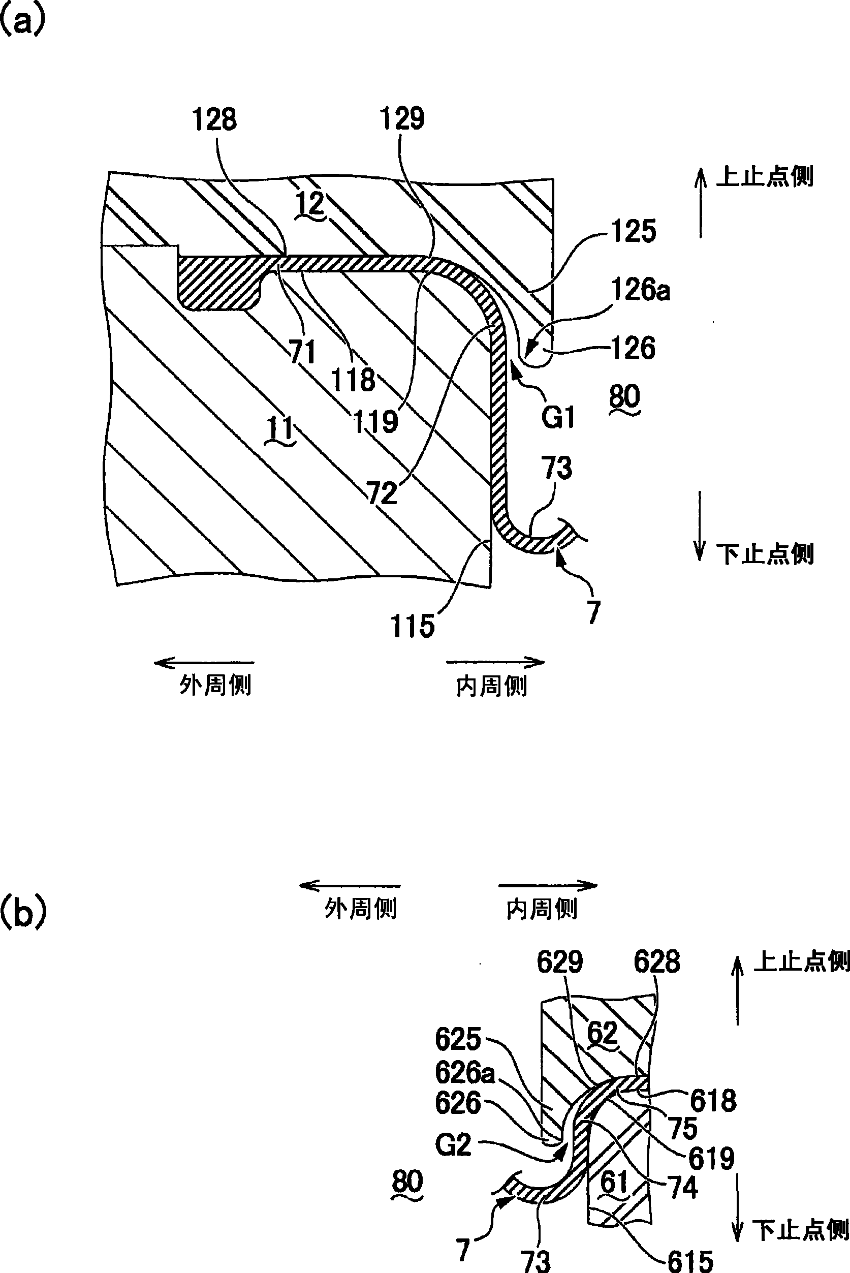
[0061] exist figure 1 In (a), the diaphragm pump device 100 (diaphragm cylinder device) of this embodiment is a pump device for sucking or discharging liquid, and has: a cylinder chamber 8 extending in the axial direction in the fixed body 10; The piston 6 inside 8, and the diaphragm 7 on the side of the fixed body 10 and the side of the piston 6 are respectively fixed on the outer peripheral side and the inner peripheral side. The diaphragm 7 divides and forms a chamber 80 for fluid inflow and outflow in the cylinder chamber 8 . In addition, in the diaphragm pump device 100, a driving device 5 for driving the piston 6 along the axial direction of the cylinder chamber 8 i...

Embodiment approach 2

[0094]In Embodiment 1 above, the diaphragm cylinder device to which the present invention is applied is applied to the diaphragm pump device. An example of an actuator that displaces a piston in the axial direction and outputs the displacement to the outside.

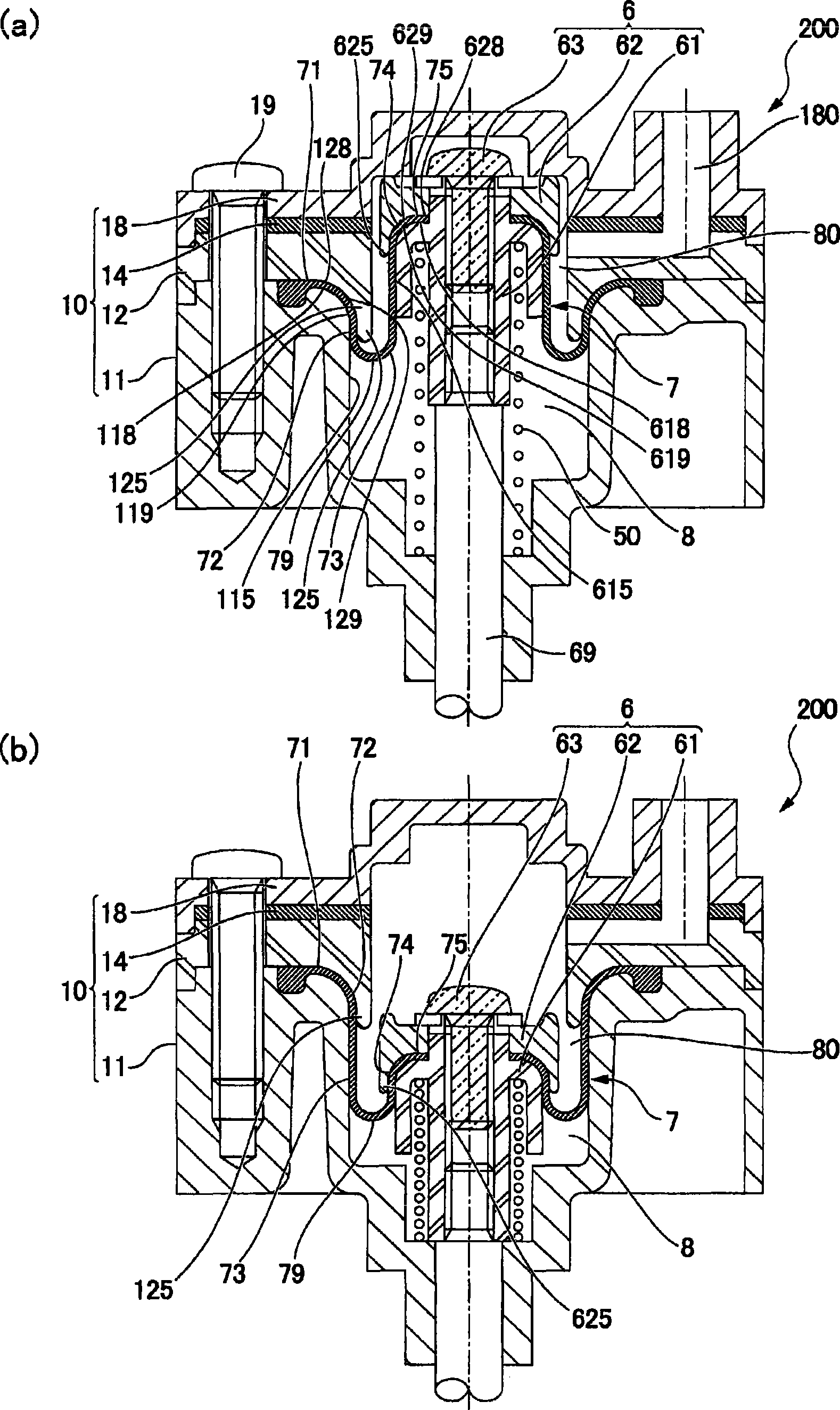
[0095] image 3 (a), (b) are longitudinal sectional views of the actuator to which the present invention is applied, image 3 (a) shows the state of the piston at the top dead center, image 3 (b) shows the state where the piston is at the bottom dead center. Figure 4 It is an explanatory diagram schematically showing the operation of the actuator to which the present invention is applied. In the actuator of this embodiment, the configuration as a diaphragm cylinder device is the same as that of Embodiment 1. Therefore, in order to make the corresponding relationship easy to understand, the same reference numerals are assigned to the parts having common functions as much as possible.

[0096] exist image 3 In (a)...


PUM


Abstract

A diaphragm cylinder device capable of improving performance characteristic of pump device or actuator by preventing the diaphragm from unnecessary deformation. In a diaphragm pump device (100), contrary to an outer peripheral side ring portion (72) of the diaphragm (7) disposed between an outer peripheral side miantained portion (71) and a free-deformation portion (73), an outer peripheral side deformation restricting part (125) for restricting deformation of an outer peripheral side ring portion (72) displaced in chamber (80), and contrary to inner peripheral side ring portion (74) of the diaphragm (7) disposed between an inner peripheral side miantained portion (71) and a free-deformation portion (73), an inner peripheral side deformation restricting part (625) for restricting deformation of the inner peripheral side ring portion (74) is displaced in chamber (80). So, when the piston (6) shifts, the outer peripheral side ring portion (72) and the inner peripheral side ring portion (74) of the diaphragm (7) generate no unnecessary deformation.

Description

technical field [0001] The present invention relates to a diaphragm cylinder arrangement using a so-called rolling diaphragm. Background technique [0002] In various cylinder devices, such as Figure 5 As shown in (a) and (b), the diaphragm cylinder device using a rolling diaphragm has: a cylinder chamber 8 formed on a fixed body 10, a piston 6 arranged in the cylinder chamber 8, and an outer peripheral side and an inner peripheral side. The diaphragm 7 fixed on the side of the cylinder chamber 8 and the side of the piston 6 respectively divides the chamber 80 for fluid inflow and outflow in the cylinder chamber 8 by the diaphragm 7 (refer to Patent Documents 1, 2, 3, 4). [0003] In the cylinder device thus constituted, the central portion in the radial direction of the diaphragm 7 becomes the deformable portion 73, and the diaphragm 7 is deformed in conjunction with the displacement of the piston, so that the folded portion 79 having a U-shaped cross section moves, and th...

Claims


Application Information

Patent Timeline
Patent Type & Authority Applications(China)
IPC IPC(8): F15B15/10
CPCF15B15/10
Inventor 村松健次
Owner SANKYO SEIKI MFG CO LTD
Learn More