A way of applying auxiliary regulation voltage ac
A technology for adjusting voltage and auxiliary signals, applied to circuits, discharge tubes, electrical components, etc., to improve analysis performance and efficiency
- Summary
- Abstract
- Description
- Claims
- Application Information
AI Technical Summary
Problems solved by technology
Method used
Image
Examples
Embodiment 1
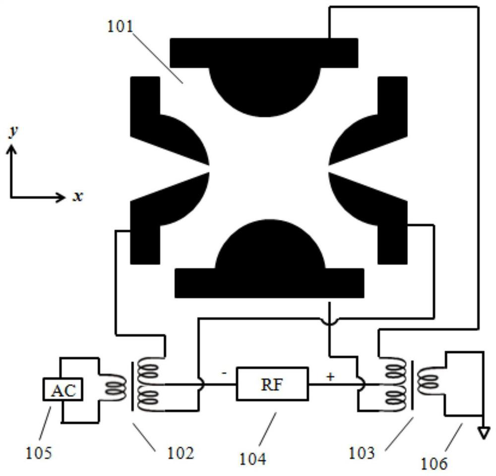
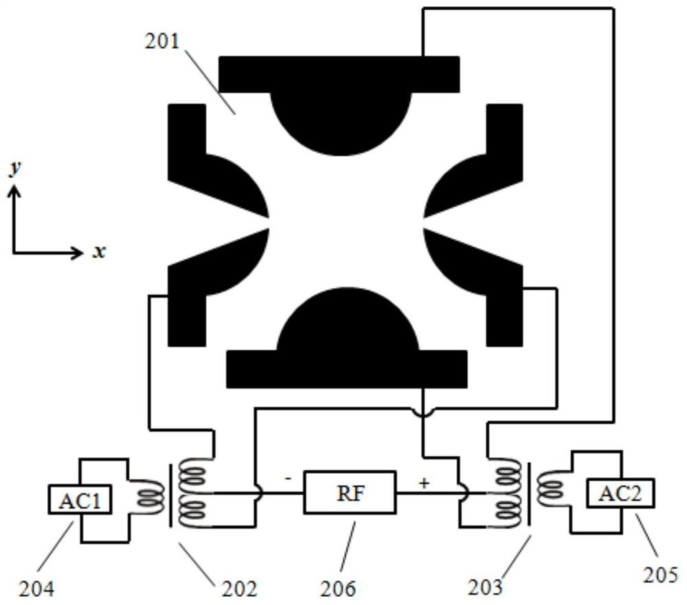
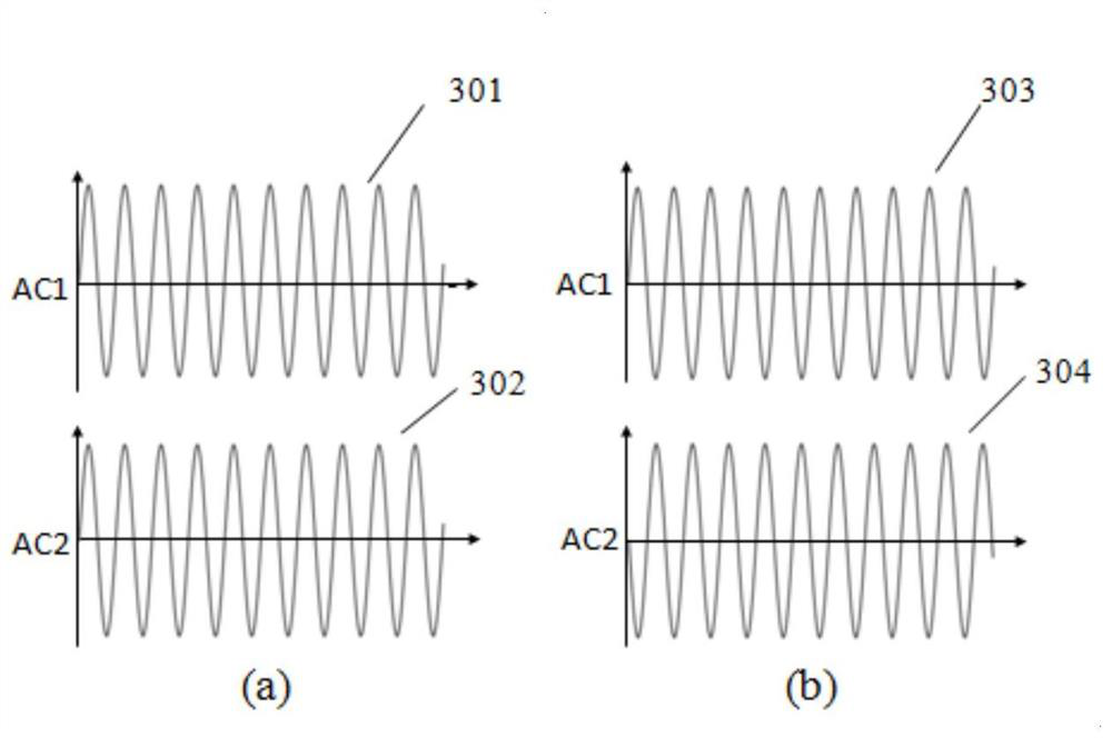
[0024] A method of applying auxiliary regulation voltage AC, the specific method is as follows figure 2 shown. 201 is a linear ion trap with a semicircular arc electrode, 202 and 203 are secondary coils, 204 is an excitation signal AC1, 205 is an auxiliary signal AC2, and 206 is a radio frequency power supply. In this embodiment, the excitation signal AC2 is coupled to the negative end of the radio frequency power supply through the secondary coil 202, and applied to the electrode in the x direction; the auxiliary signal AC2 is coupled to the positive end of the radio frequency RF through the secondary coil 203, and applied on the electrodes in the y direction. During the mass analysis process, the excitation signal AC1 works only in the ion collision-induced dissociation stage or the scanning stage, and the auxiliary signal AC2 only works in the ion collision-induced dissociation stage or the ion cooling stage. The voltage signals of AC1 and AC2 are as follows: image 3 As...
Embodiment 2
[0026] A method of applying auxiliary regulation voltage AC, the specific method is as follows Figure 4 shown. Among them, 401 is a semicircular electrode linear ion trap, 402 is a radio frequency power supply RF, 403, 404, 407, 408 are secondary coils, 405 is an excitation signal AC1, 406 is an auxiliary signal AC2, 409 and 410 are corresponding inductance matching grounding end. In this embodiment, the excitation signals AC1 and AC2 are coupled to the negative end of the radio frequency power supply through the secondary coils 403 and 404 respectively, and applied to the electrodes in the x direction. Since the electrodes in the x direction are coupled with two AC signals, two inductance matching ground terminals need to be coupled to the corresponding electrodes in the y direction to ensure that the radio frequency RF signals on the electrodes in the x direction and the electrodes in the y direction are balanced. The difference between this example and Implementation 1 i...
Embodiment 3
[0028] A method of applying auxiliary regulation voltage AC, the specific method is as follows Figure 5 shown. Among them, 501 is a semicircular electrode linear ion trap, 502 is a radio frequency power supply RF, 503, 504, 507, and 508 are secondary coils, 505 is an excitation signal AC1, 506 is an auxiliary signal AC2, 509 is an auxiliary signal AC3, and 510 is a corresponding The inductance is matched to ground. The difference between this example and the above-mentioned embodiments is that two-way auxiliary signals AC2 and AC3 are applied. The excitation signal AC1 and the auxiliary signal AC2 are respectively coupled to the negative end of the radio frequency RF through the secondary coils 503 and 504, and applied to the electrodes in the x direction; the auxiliary signal AC3 is coupled to the positive end of the radio frequency RF through the secondary coil 507, and at the same time 510 The inductance is matched to the ground terminal to ensure that the radio frequenc...
PUM
 Abstract
Description
Claims
Application Information
 - R&D
- Intellectual Property
- Life Sciences
- Materials
- Tech Scout
- Unparalleled Data Quality
- Higher Quality Content
- 60% Fewer Hallucinations
Browse by: Latest US Patents, China's latest patents, Technical Efficacy Thesaurus, Application Domain, Technology Topic, Popular Technical Reports.
© 2025 PatSnap. All rights reserved.Legal|Privacy policy|Modern Slavery Act Transparency Statement|Sitemap|About US| Contact US: help@patsnap.com


