
Novel vessel washing device

A technology for cleaning devices and containers, which is applied in the directions of cleaning hollow objects, cleaning methods and utensils, chemical instruments and methods, etc., can solve the problems of low work efficiency, low cleaning efficiency, and difficulty in meeting various needs, and achieves convenient operation and structure. Simple, improved cleaning speed and quality

Inactive Publication Date: 2018-06-26
广州酬建电器有限公司
View PDF0 Cites 0 Cited by
  • Summary
  • Abstract
  • Description
  • Claims
  • Application Information

AI Technical Summary

Problems solved by technology

[0002] A container refers to a container for loading items, such as a box, a can, an altar, etc. After the container is taken out of the stored items, most of the inner walls of the container need to be cleaned. The existing ones usually use brushes and other items to clean manually. Manual operation requires a lot of labor, and the cleaning efficiency is low. At present, there are also equipment that can automatically clean the inner wall of the container, but it is difficult to meet the cleaning of the inner wall of different sizes of containers, it is difficult to meet various needs, and the work efficiency is low.

Method used

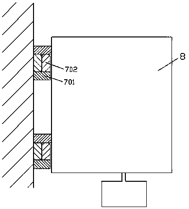
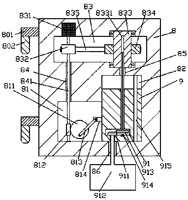

Image

  • Novel vessel washing device
  • Novel vessel washing device
  • Novel vessel washing device

Examples


Embodiment Construction

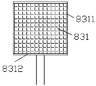
[0012] Such as Figure 1-Figure 3 As shown, a novel container cleaning device of the present invention includes a detachable main frame 8 installed on the wall, and support arms 701 are respectively fixedly installed on the upper and lower sides of the wall surface, and each of the A lock bar 702 is fixedly installed on the upper end surface of the right part of the support arm 701, and a cross arm 801 is fixedly installed on the upper and lower sides of the left end surface of the main frame 8 respectively. The length of the cross arm 801 is greater than the length of the support arm 701. A locking head 802 is fixedly installed on the lower end surface of the left side of the cross arm 801, and the locking head 802 is installed in cooperation with the angle formed between the locking bar 702 and the support arm 701, and the main frame 8 is provided inside. There is a conversion cavity 81, the right side of the conversion cavity 81 is connected with a guide groove 82 extended ...


PUM


Abstract

The invention discloses a novel vessel washing device. The device comprises a main frame which is detachably mounted on a wall body, wherein supporting arms are correspondingly fixedly mounted at theupper side and the lower right side of the surface of the wall body; a lock rod is fixedly mounted on the upper end surface of the right part of each supporting arm; transverse arms which are longer than the supporting arms are correspondingly fixedly mounted at the upper side and the lower side of the left end surface of the main frame; a locking head is fixedly mounted on the lower end surface of the left side of each transverse arm; each locking head is mounted and fit an included angle formed between the corresponding lock rod and the corresponding supporting arm; a conversion chamber is formed in the main frame; a guide groove which is upwards arranged in an extending manner is formed in the right tail side of the conversion chamber in a communication manner; a belt rotating groove which is arranged by extending toward the left side is formed in the inner wall body, at the upper side of the guide groove, of the main frame; the left side extending section of the belt rotating groove is positioned in the main frame above the top part of the conversion chamber. The device is simple in structure, convenient to operate, high in safety, and capable of increasing the vessel cleaningspeed as well as improving the vessel cleaning quality.

Description

technical field [0001] The invention relates to the technical field of container cleaning, in particular to a novel container cleaning device. Background technique [0002] A container refers to a container for loading items, such as a box, a can, an altar, etc. After the container is taken out of the stored items, most of the inner walls of the container need to be cleaned. The existing ones usually use brushes and other items to clean manually. Manual operation requires a lot of labor, and the cleaning efficiency is low. At present, there are also equipment that automatically cleans the inner wall of the container, but it is difficult to clean the inner wall of different sizes of containers, it is difficult to meet various needs, and the work efficiency is low. Contents of the invention [0003] The technical problem to be solved by the present invention is to provide a novel container cleaning device, which can solve the above-mentioned problems in the prior art. [00...

Claims


Application Information

Patent Timeline
Patent Type & Authority Applications(China)
IPC IPC(8): B08B9/087B08B13/00
CPCB08B9/087B08B13/00
Inventor 覃日雄
Owner 广州酬建电器有限公司
Learn More