
Piercing device

A technology of perforating device and perforating shaft, which is used in transportation and packaging, thin material handling, instruments, etc., can solve problems such as difficult stopping, and achieve the effect of improving stopping accuracy.

Inactive Publication Date: 2019-09-17
KYOCERA DOCUMENT SOLUTIONS INC
View PDF5 Cites 0 Cited by
  • Summary
  • Abstract
  • Description
  • Claims
  • Application Information

AI Technical Summary

Problems solved by technology

Therefore, even if braking (short-circuit braking or reverse braking) is applied during high-speed rotation, it will not stop at the same time as braking, but it will be difficult to stop at the reference position due to inertial rotation.

Method used


Image

  • Piercing device
  • Piercing device
  • Piercing device

Examples


Embodiment Construction

[0020] Next, embodiments of the present invention will be described with reference to the drawings.

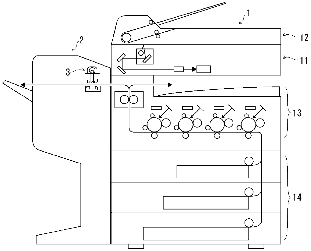
[0021] refer to figure 1 , The image forming system of this embodiment includes an image forming apparatus 1 that records and outputs a formed image on recording paper, and a post-processing that receives recording paper output from the image forming apparatus 1 and performs various post-processing on the received recording paper. device 2.

[0022] The image forming apparatus 1 is an electrophotographic copier or MFP (Multifunction Peripheral / Printer / Product, multifunctional printer / product / peripheral), etc., and includes a document reading unit 11, a document feeding unit 12, an image forming unit 13 and recording paper supply unit 14 . The image forming apparatus 1 executes image forming operations such as a copy job, a scan job, a facsimile transmission job, and a print job based on an operation accepted while logged in through user authentication.

[0023] Document rea...


PUM


Abstract

Provided is a hole punching apparatus that is capable of improving the accuracy of stopping at a target reference position. The hole punching apparatus executes a hole-punching process and a braking process, and includes a rotation-detecting unit and a brake-control unit. The hole-punching process punches punch holes by rotating a hole-punching shaft from a reference position. The brake-control unit intermittently turns ON and OFF a short-circuit brake in the braking process. The brake-control unit sets a braking period for turning ON the brake according to the rotation position and rotation speed of the hole-punching shaft that is measured based on the rotation-position signal so that the braking period tends to become longer as the rotation position becomes closer to the reference position, and tends to become longer as the rotation speed becomes faster.

Description

technical field [0001] The present invention relates to a punching device for punching holes in recording paper. Background technique [0002] As a punching device for punching a hole in recording paper, there is known a punching tool that punches a hole in recording paper by moving up and down, a motor for punching, and a vertical motion conversion unit that converts the rotation of the motor for punching into the vertical motion of the punching blade. installation. [0003] Usually, punching by a punching device is usually performed in a short time of several tens of milliseconds, and thus is accompanied by a large load fluctuation. Therefore, in typical techniques, many DC motors are used as motors for piercing, but DC motors have a large inertia. Therefore, even if braking (short-circuit braking or reverse braking) is applied during high-speed rotation, it will not stop at the same time as braking, but it will be difficult to stop at the reference position due to inert...

Claims


Application Information

Patent Timeline
Patent Type & Authority Patents(China)
IPC IPC(8): B65H35/06
CPCB65H35/06B65H2701/37G03G15/6582G03G2215/00818
Inventor 加美长诚治
Owner KYOCERA DOCUMENT SOLUTIONS INC
Learn More