
Objective switch-over device

A switching device and objective lens technology, applied in the direction of installation, microscopes, instruments, etc., can solve the problems of non-smoothness between the leaf spring and the ball, poor position reproducibility, positioning impact, etc., achieve small shaking, small vibration, improve product quality and The effect of durability

Inactive Publication Date: 2006-02-01
OLYMPUS OPTICAL CO LTD
View PDF1 Cites 0 Cited by
  • Summary
  • Abstract
  • Description
  • Claims
  • Application Information

AI Technical Summary

Problems solved by technology

For this reason, complex adjustments are required in the mechanism for electrically detecting the stop position of the motor, and complex control of the mechanism for braking the motor drive source is required.
[0007] In addition, in the detent mechanism, the gap between the leaf spring and the ball is not smooth, so grinding occurs after repeated use, poor position reproducibility, or damage to the leaf spring
[0008] In addition, in the objective lens switching device (converter) of the swing method (the swing method improves the operability when marking the abnormal part on the sample), the angle between the objective lens that avoids the optical axis and the optical axis is about 60°. °, Therefore, in order to limit the rotation force to maintain the posture, a large force is required, a large space is required in the detent mechanism, and a large impact is generated when positioning

Method used


Image

  • Objective switch-over device
  • Objective switch-over device
  • Objective switch-over device

Examples


Embodiment Construction

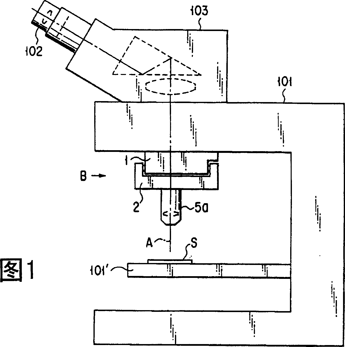
[0097] Fig. 1 is a diagram showing the structure of a microscope employing an objective lens switching device according to a first embodiment of the present invention. As shown in FIG. 1 , on the microscope body 101 , the mounting part 1 of the objective lens switching device is fixed by a tongue and groove mechanism. On the main body 101 of the microscope, a lens barrel 103 equipped with an eyepiece 102 and a stage 101' on which an observation sample S is placed are installed. On the attachment member 1 of the present objective lens switching device, a rotating member 2 is supported as described later, and an objective lens 5a (and an objective lens 5b) on which the objective lens is located on the observation optical axis A is attached to the rotating member 2 .

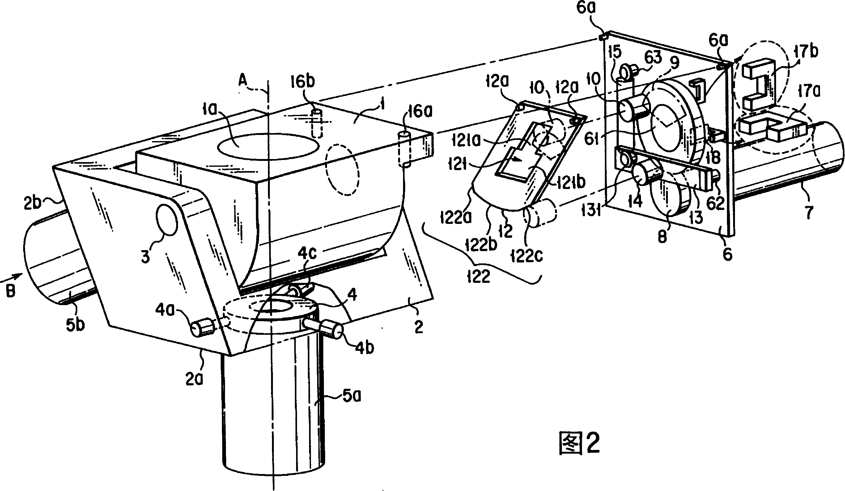
[0098] Fig. 2 is an exploded perspective view showing the structure of the above-mentioned objective lens switching device. The mounting part 1 is installed on the body 101 of optical devices such as the above-men...


PUM


Abstract

The objective changing-over apparatus of the present invention mounted on a microscope, for changing over two objectives on the microscope optical axis by electric power using a driving source comprises a rotation member to fit the two objectives, and two abutting members for limiting the rotation range of the rotation member, a transmission mechanism having a rotation area including a transmission area for transmitting the force and larger than the rotation range of the rotation member limited by the abutting member, for transmitting the force from the driving source to the rotation member by the transmission area.

Description

technical field [0001] The invention relates to an objective lens switching device, which is used in optical devices such as microscopes, selects an objective lens with a required magnification from several objective lenses according to the observed object, and positions it on the observation optical path by electric power. Background technique [0002] The existing device is to drive the motor with a predetermined voltage to rotate the movable part of the converter. At the same time, a mechanical joint mechanism is provided between the movable part of the converter and the fixed part to stop the rotation of the movable part of the rotator. . This joint mechanism mechanically engages the converter movable part with the fixed part every time the optical axis of each objective lens mounted on the converter movable part reaches a position coincident with the observation optical axis of an optical device such as a microscope, and maintains the position. Location. [0003] Fig....

Claims


Application Information

Patent Timeline
Patent Type & Authority Patents(China)
IPC IPC(8): G02B7/14G02B21/02G02B7/16G02B21/24
CPCG02B21/248
Inventor 长谷川和宏
Owner OLYMPUS OPTICAL CO LTD
Learn More