Discretely controlled micromirror device having multiple motions

a micromirror and motion control technology, applied in the field of micromirrors, can solve the problems of difficult combination with known semiconductor electronics technologies such as mos, cmos, and difficult to combine with digital or discrete control, and achieve the effect of simple motion control

Active Publication Date: 2008-09-18
STEREO DISPLAY
View PDF86 Cites 4 Cited by
  • Summary
  • Abstract
  • Description
  • Claims
  • Application Information

AI Technical Summary

Benefits of technology

[0032]The micromirrors in array of the DCMs have independently controlled motions to make a spatial light modulator. The one translational degree of freedom motion of the DCM is controlled to retract or elevate the micromirror to remove the phase aberration of an optical system. The one or two rotational degrees of freedom motion of the DCM is controlled to control light intensity and / or to scan a field of regard. By using both rotational degree of freedom motion and translational degree of freedom motion of the DCM, a fine spatial light modulator can be provided.
[0033]The DCM of this invention has advantages including: (1) the DCM provides multiple motions of the micromirror; (2) the DCM can be controlled in a low driving voltage; (3) simple motion control is achieved by applying digital control; (4) the DCM has a fine motion control of the micromirror using multiple supports and electrodes; (5) only single voltage is needed for driving the control circuitry; and (6) the micromirror is controlled discretely.

Problems solved by technology

The analog control requires a fine voltage control and is more complex than the digital or discrete control and difficult to combine with known semiconductor electronics technologies such as MOS, CMOS, etc.
Even in the case using digital addressing for this system, it still has the limitation in the translational and rotational ranges of the micromirror in order to provide multiple motions of the micromirror while avoiding the snap-down phenomenon.
The high driving voltage is another disadvantage in controlling the micromirror motion with continuous displacement actuated by electrostatic force.

Method used


Image

  • Discretely controlled micromirror device having multiple motions
  • Discretely controlled micromirror device having multiple motions
  • Discretely controlled micromirror device having multiple motions

Examples


Embodiment Construction

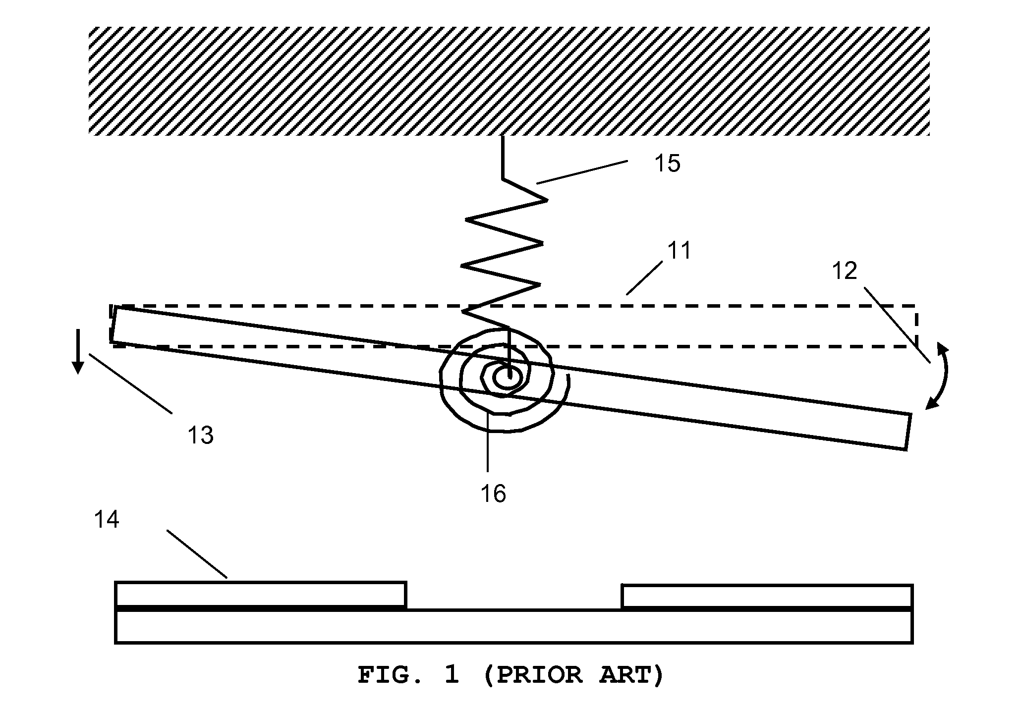
[0049]FIG. 1 shows schematic diagram of the prior art of the micromirror control system. A micromirror 11 is controlled to have a continuous rotation 12 or translation 13, which is determined by the equilibrium between electrostatic force from the electrode 14 and the micromirror 11 and elastic force of the translational spring 15 and the rotational spring 16. The micromirror 11 is rotated along the hinge supported by the supporting structure. Since the motion is determined by the static equilibrium of the electrostatic and elastic forces, complex analog control with active feedback is required to have a fine control of the motion.

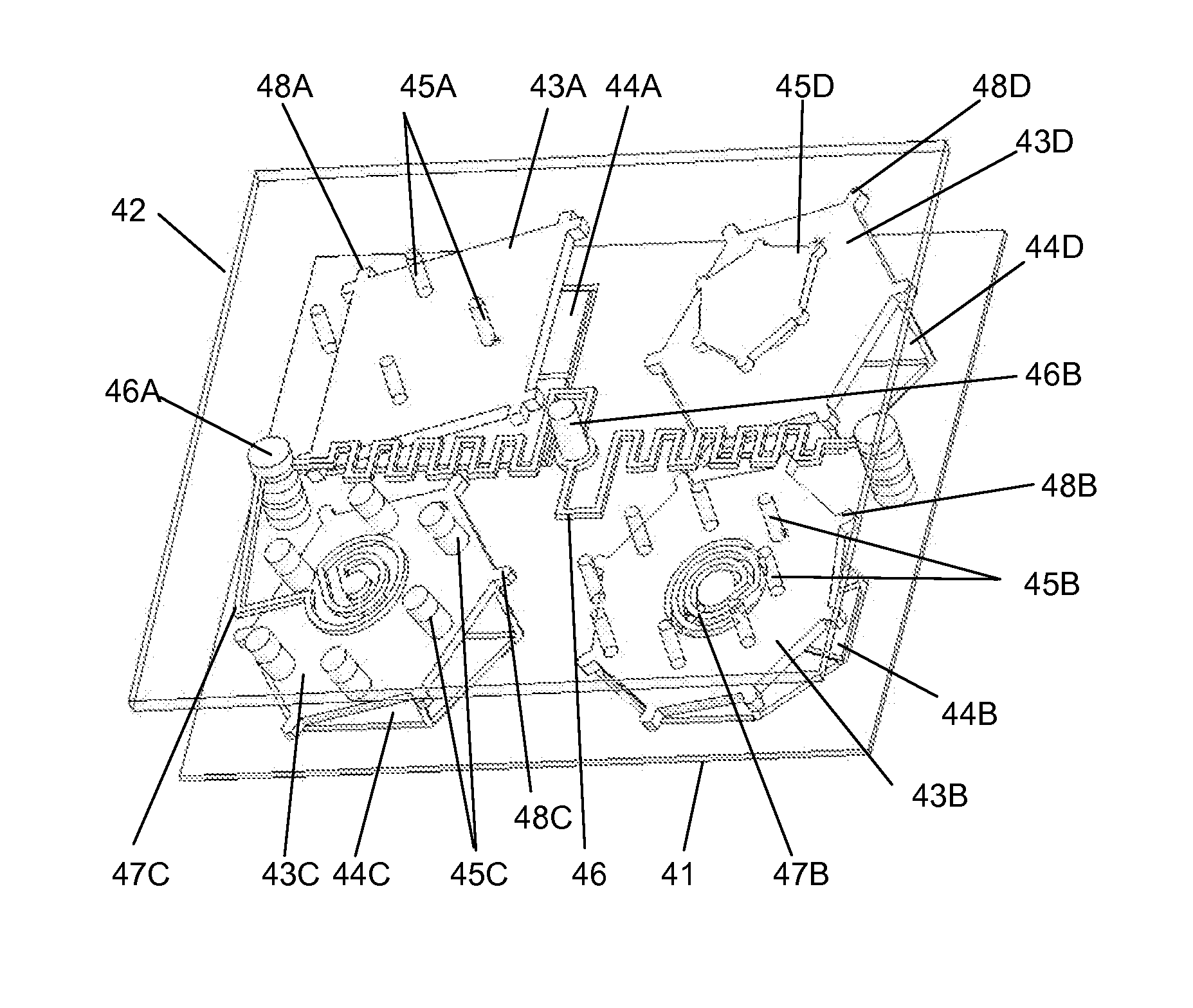
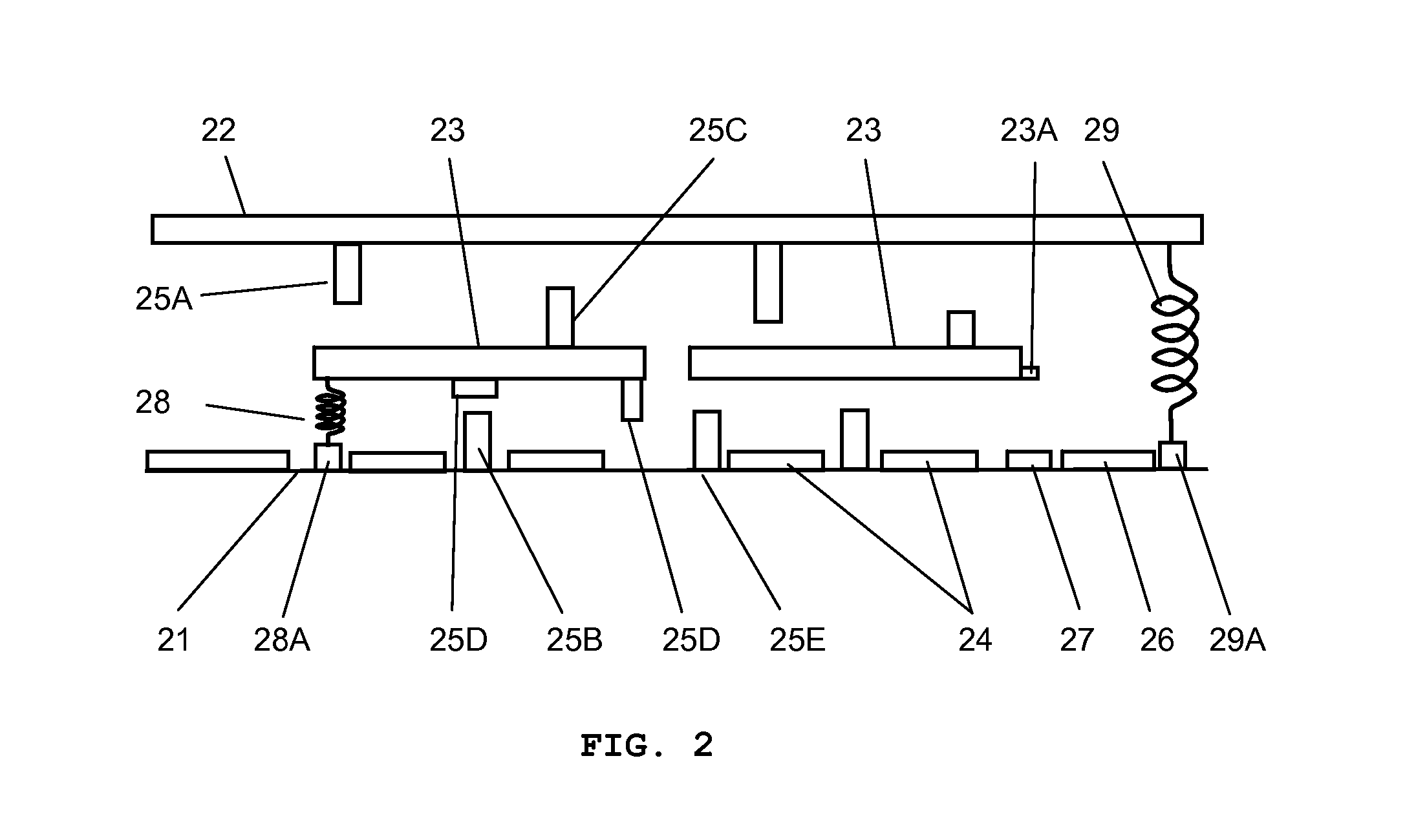
[0050]On the other hand, the Discretely Controlled Micromirror (DCM) of the present invention has simpler control system. Once the motion is defined and programmed in the micromirror structure, the control is just applying the on / off voltage for desired channel with respect to the desired motion. No feedback is required and the motion is reproducible regar...


PUM


Abstract

A discretely controlled micromirror device provides multiple motions of a micromirror using stepper plate and micromirror bottom support. The discretely controlled micromirror device can be controlled in a low driving voltage. Also, simple motion control is applied by digital controlling and only single voltage is needed for driving the micromirror motion.

Description

FIELD OF INVENTION[0001]The present invention relates to micromirror in general and more specifically micromirror control and motion generation.BACKGROUND OF THE INVENTION[0002]Micromirrors may be used in various optical applications instead of, or in addition to, conventional optoelectronic devices. It is desirable to have capability to move the micromirrors by rotation and translation with very fine control.[0003]Since the micro-electro mechanical systems (MEMS) were developed, many applications in MEMS have been developed and used. Micromirror device is the one of the major development in MEMS field. Devices and application using micromirrors are developed and used in various fields such as optical communication and display. As the applications of micromirrors grow rapidly, the demand on controlling micromirror device increases. It is desirable to have the motion control of the micromirror with many degrees of freedom and simple driving method.[0004]A phase-only piston-style micr...

Claims


Application Information

Patent Timeline
Patent Type & Authority Applications(United States)
IPC IPC(8): G02B26/08
CPCG02B26/0841G02B26/0866G02B26/085
Inventor KIM, HYE YOUNGGIM, DONG WOOSOHN, JIN YOUNGCHO, GYOUNG ILSEO, CHEONG SOO
Owner STEREO DISPLAY
Why Eureka
Try Eureka