Robot system

A robot system and robot hand technology, applied in the field of robot systems, can solve the problems of complexity, limited configuration accuracy, high-tech robot arm or robot hand motion control, and achieve the effect of simplifying motion control and improving motion reliability.

Active Publication Date: 2014-02-12
YASKAWA DENKI KK
View PDF6 Cites 4 Cited by
  • Summary
  • Abstract
  • Description
  • Claims
  • Application Information

AI Technical Summary

Problems solved by technology

The motion control of the robotic arm or robotic hand used for this purpose is high tech and complex
In addition, such complicated motion control limits the positioning accuracy (positioning accuracy) of the workpiece to the workpiece setting position.
Therefore, there is a problem that it is difficult to obtain sufficient operational reliability

Method used


Image

  • Robot system
  • Robot system
  • Robot system

Examples


Embodiment Construction

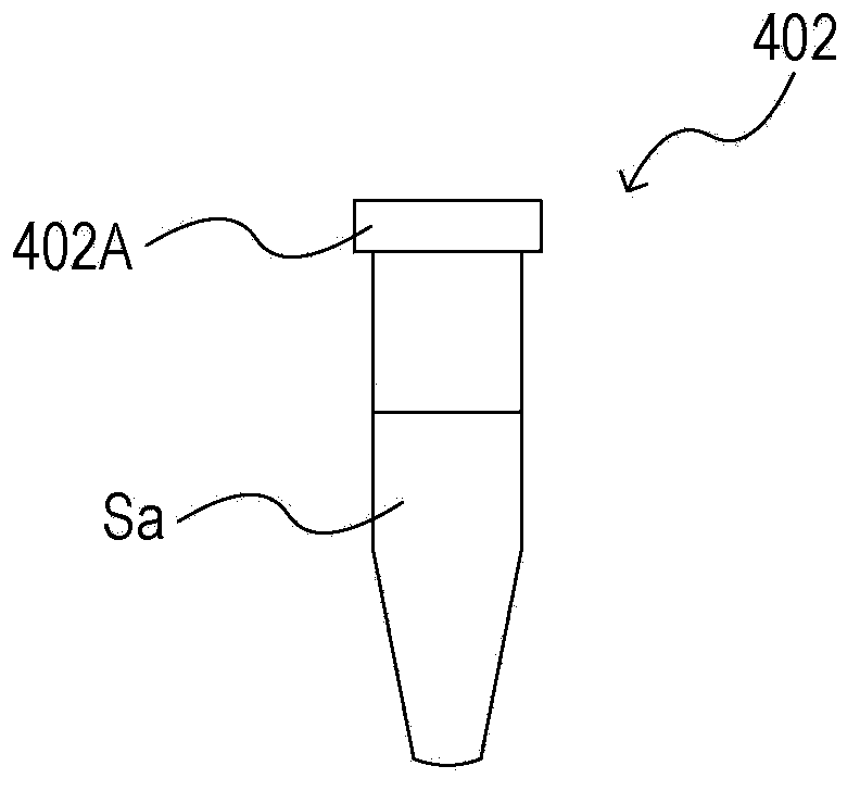
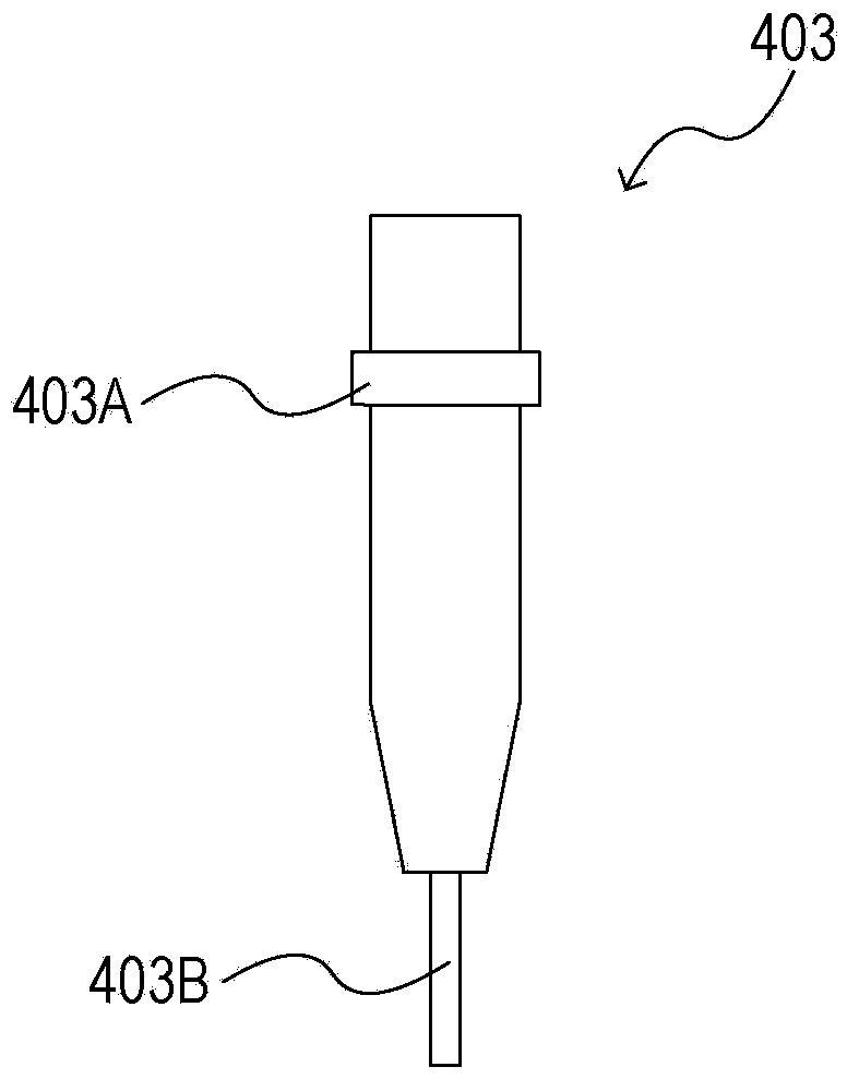
[0033] Hereinafter, an embodiment will be described with reference to the drawings. In this embodiment, a series of work examples by the robot system are shown. This work includes a work of inserting a pipe into an insertion hole provided in a rotor of the centrifugal separator and a work of pulling out the pipe from the insertion hole.

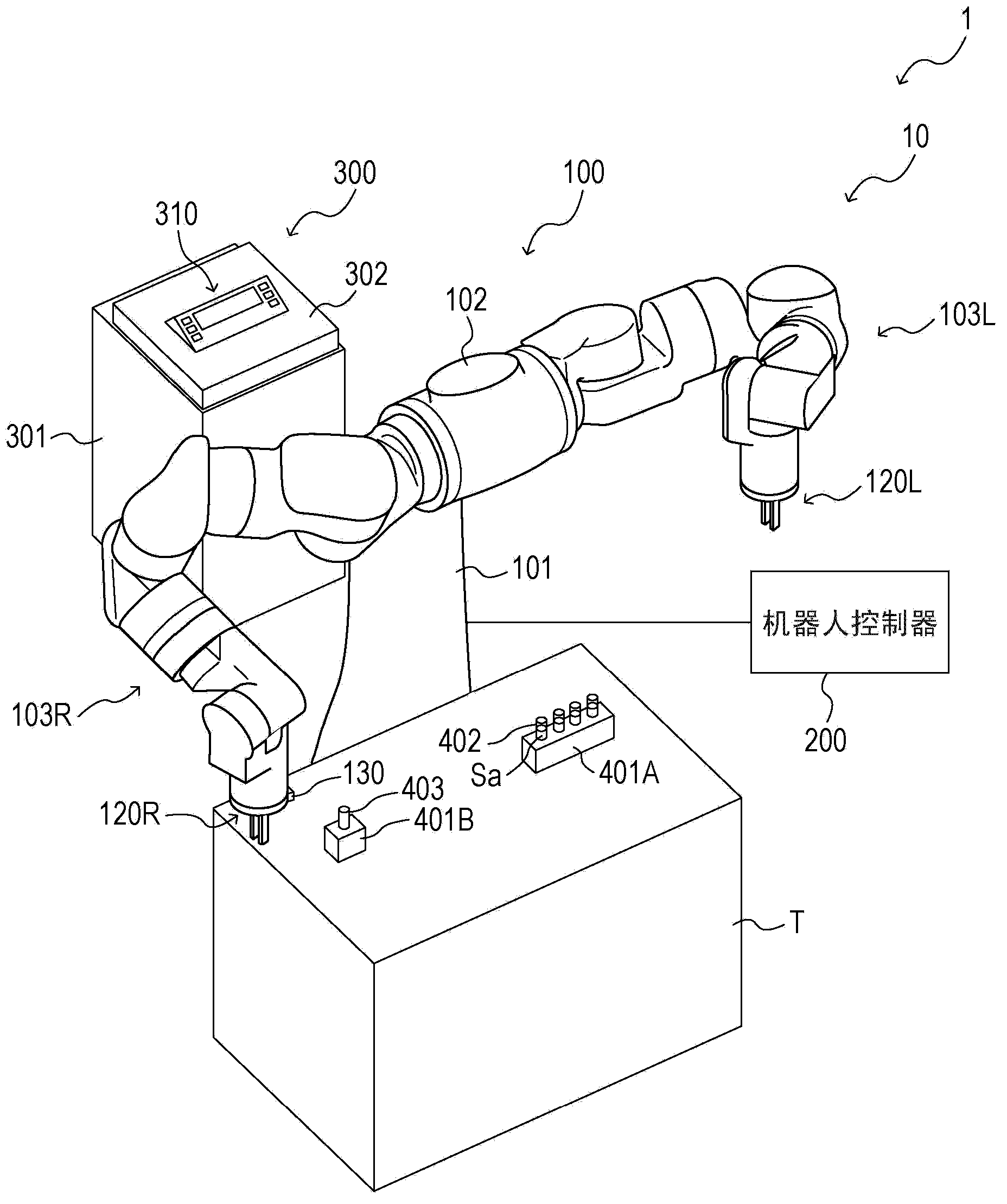
[0034] First, refer to figure 1 An example of the overall configuration of the robot system according to this embodiment will be described.

[0035] like figure 1 As shown, the robot system 1 of the present embodiment has a robot system 10 and a centrifugal separator (also referred to as a centrifuge, centrifuge, centrifuge, etc.) 300 . In addition, the centrifugal separator 300 corresponds to a rotating device.

[0036] The robot system 10 has a robot body 100 and a robot controller 200 . The robot main body 100 and the robot controller 200 are connected by wire or wirelessly in a mutually communicable manner. In addition, a robot cont...


PUM


Abstract

A robot system includes: a robot arm; a robot hand provided on the robot arm; a contact unit provided on the robot hand for rotating a rotation body of a rotation device which includes the rotation body capable of housing a work and a fixed part rotatably supporting the rotation body and which performs a predetermined process on the work; a detection unit configured to detect a detection target part provided on the rotation body; and a first control unit configured to control operation of the robot arm and the robot hand so that the contact unit rotates the rotation body up to a predetermined rotational position according to a result of detecting the detection target part by the detection unit.

Description

[0001] Cross References to Related Applications [0002] This application is based on Japanese Patent Application No. 2012-161017 submitted to the Japan Patent Office on July 19, 2012, and therefore the entire content of said Japanese Patent Application is incorporated herein by reference. technical field [0003] The present invention relates to robotic systems. Background technique [0004] Japanese Patent Application Laid-Open No. 2011-251828 discloses a processing system including a robot system. In this processing system (food product conveying system), a workpiece (food product) manufactured by a food product manufacturing apparatus is conveyed to a position close to a robot (transportation robot) by a belt conveyor. Afterwards, a camera (CCD camera) takes an image of the workpiece. Thereby, the conveyance speed and / or position of a workpiece are detected. Then, based on the detection result, the robot hand of the robot holds the workpiece and transfers it to a stor...

Claims


Application Information

Patent Timeline
Patent Type & Authority Applications(China)
IPC IPC(8): B25J9/08B25J9/18B04B5/10
CPCB25J9/0087G01N35/0099B25J9/1612B04B2011/046B04B5/0414B04B13/00G01N2035/00495
Inventor 梅野真堀内智之巢山崇
Owner YASKAWA DENKI KK
Why Eureka
Try Eureka