Reactive headrest system for disabled individuals

Inactive Publication Date: 2013-10-03
WISYS TECH FOUND
View PDF34 Cites 4 Cited by
  • Summary
  • Abstract
  • Description
  • Claims
  • Application Information

AI Technical Summary

Benefits of technology

[0005]The present inventor has recognized that the motion of common position relief headrests can promote an undesired elevation of the patient's head and, further, that hypertonic extension often applies significant off-axis forces which can jam conventional position relief headrests. In this regard, the present invention provides a pos

Problems solved by technology

Hypertonicity of the neck muscles can result in neck hyper-extension and injury to an individual if their head is not properly supported during the extension episodes.
A standard headre

Method used


Image

  • Reactive headrest system for disabled individuals
  • Reactive headrest system for disabled individuals
  • Reactive headrest system for disabled individuals

Examples


Embodiment Construction

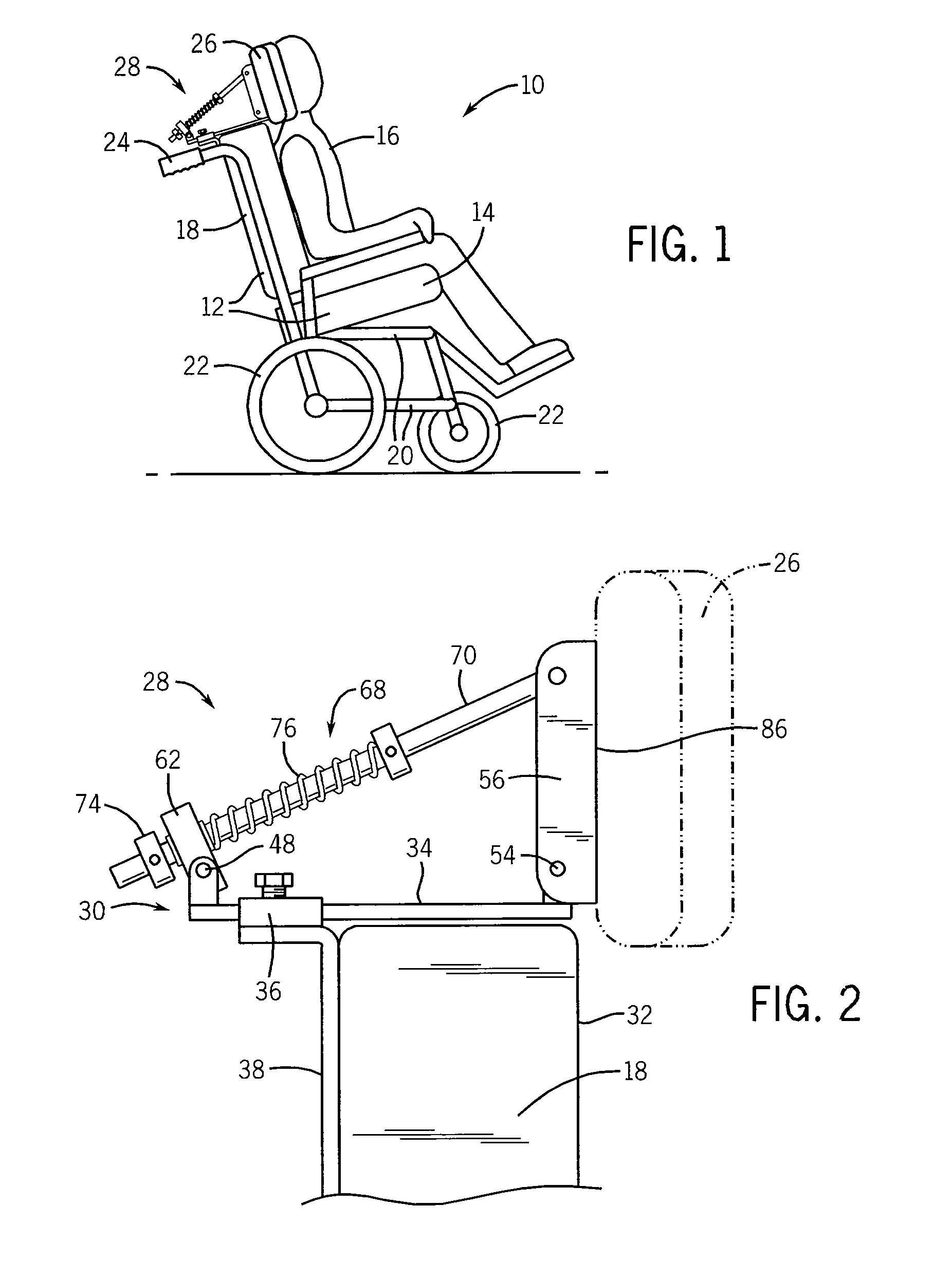
[0036]Referring now to FIG. 1, a wheelchair 10 may provide a seat assembly 12 having a substantially horizontal seat pan 14 on which a patient 16 may sit. A seatback 18 may extend upward from a rear of the seat pan 14 to support the back of the seated patient 16 thereagainst.

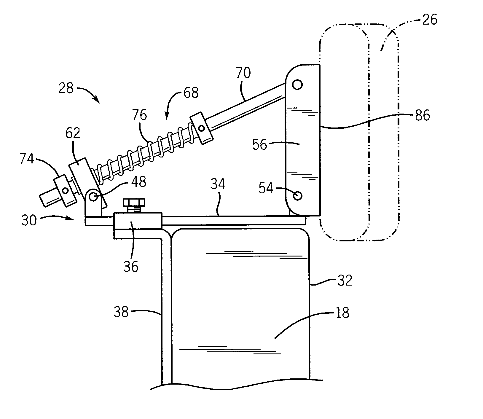
[0037]The seat pan 14 and seatback 18 of the seat assembly 12 may be joined by means of a seat frame 20 to wheels 22 positioned beneath the seat assembly 12 so that the seat assembly 12 maybe moved by rolling the wheels 22 over a surface, for example, as pushed by an assistant gripping hand grips 24 extending rearward from the upper edge of the seatback 18. The patient's head may be supported at its back by a headrest cushion 26 attached to a headrest assembly 28 of the present invention.

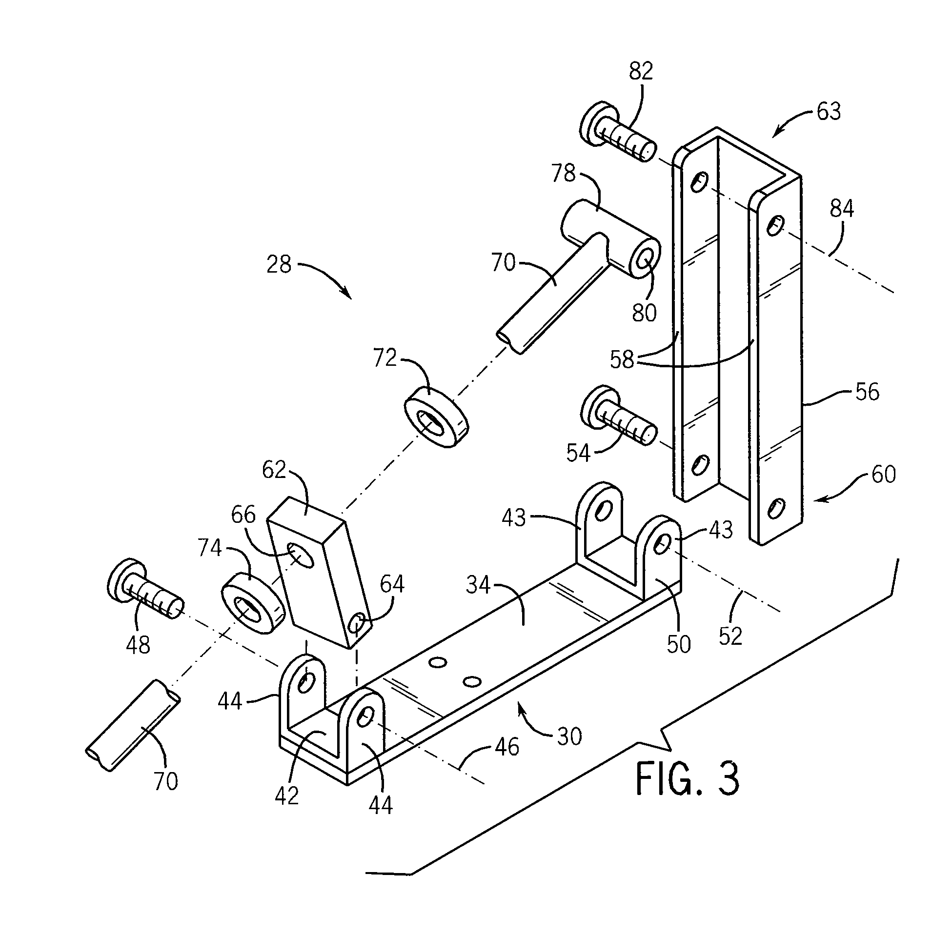
[0038]Referring now to FIG. 2, the headrest assembly 28 may provide a base bracket 30 extending generally horizontally along the top of the seatback 18 in a direction generally perpendicular to a support face 32 of the seatback ...


PUM


Abstract

A headrest assembly for assisting individuals with hypertonic extension pattern provides a pivoting support that better matches the pivoting motion of the patient's head in backward extension. A restoring spring absorbs and dissipates the energy of the extension and provides adjustable spring restoring force.

Description

CROSS-REFERENCE TO RELATED APPLICATIONS[0001]This application claims the benefit of U.S. provisional application 61 / 578,580 filed Dec. 21, 2011 and hereby Incorporated by reference.BACKGROUND OF THE INVENTION[0002]The present invention relates to a headrest for use on wheelchairs and the like to support the heads of individuals with hypertonic extension patterns and, in particular, to a headrest providing improved position relief during extension episodes.[0003]Hypertonia is an abnormal increase in muscle tension that can be expressed in uncontrollable muscle spasms and that may be associated with disabilities such as cerebral palsy or the like. Hypertonicity of the neck muscles can result in neck hyper-extension and injury to an individual if their head is not properly supported during the extension episodes.[0004]A standard headrest, for example, incorporated into a wheelchair or other similar device, can be inadequate for dissipating the force of hypertonic extension because of i...

Claims


Application Information

Patent Timeline
IPC IPC(8): A61G5/12
CPCA61G2005/121A61G5/12A61G5/121
Inventor STEPHENS, CHARLES JOSEPH
Owner WISYS TECH FOUND
Why Eureka
Try Eureka