
Building steel structure connection device and connection structure

A technology of structural connection and construction steel, applied in the direction of building structure, construction, etc., can solve the problem of poor firmness of columns and beams, and achieve the effect of good firmness

Active Publication Date: 2020-03-10
吉林省飞达杭萧建筑科技有限公司
View PDF2 Cites 0 Cited by
  • Summary
  • Abstract
  • Description
  • Claims
  • Application Information

AI Technical Summary

Problems solved by technology

[0004] The purpose of the present invention is to provide a connection structure to improve the problem of poor firmness after the column and the beam are connected

Method used


Image

  • Building steel structure connection device and connection structure
  • Building steel structure connection device and connection structure
  • Building steel structure connection device and connection structure

Examples


Embodiment 1

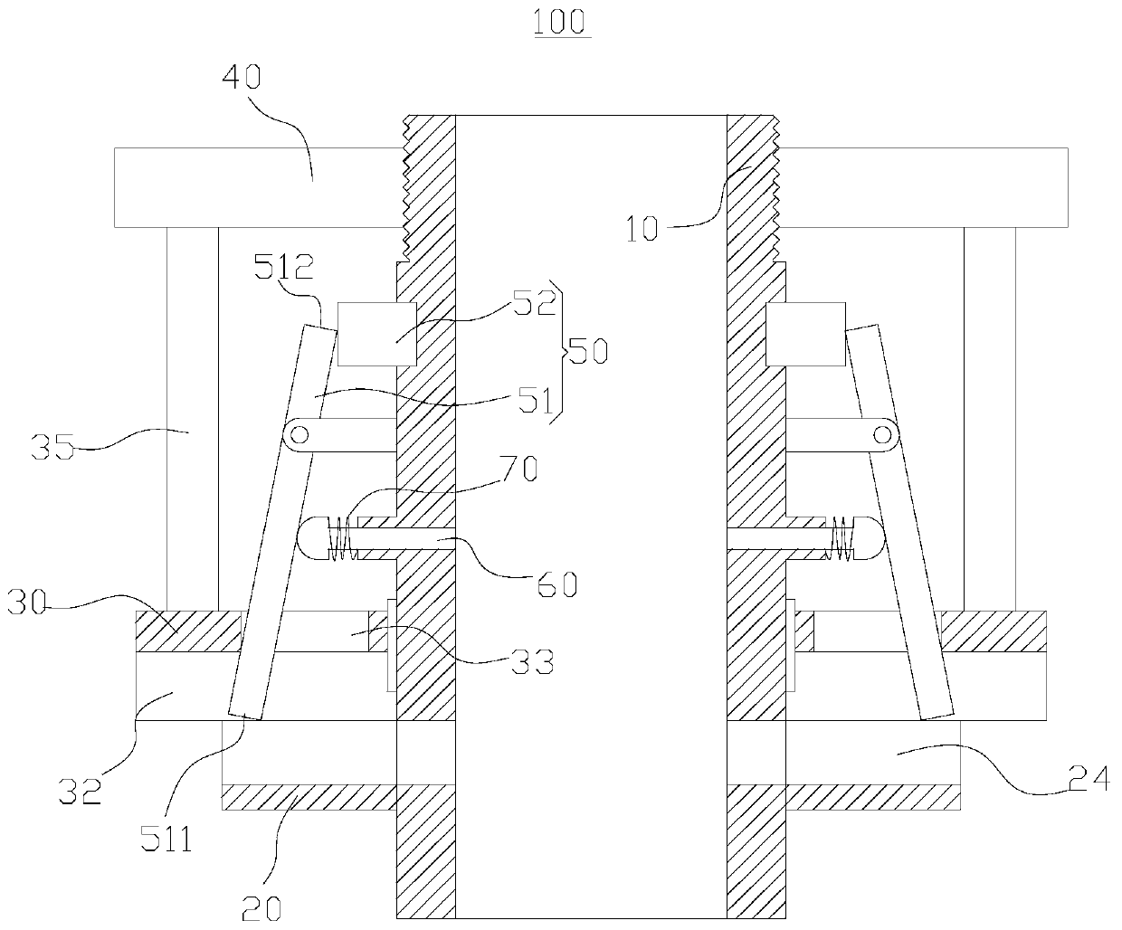
[0044] Such as figure 1 As shown, this embodiment provides a building steel structure connection device 100 for connecting a column 210 and a beam 220, which includes a center sleeve 10, a first clip body 20, a second clip body 30, a driving device 40, and a clamping device 50 and locking member 60.

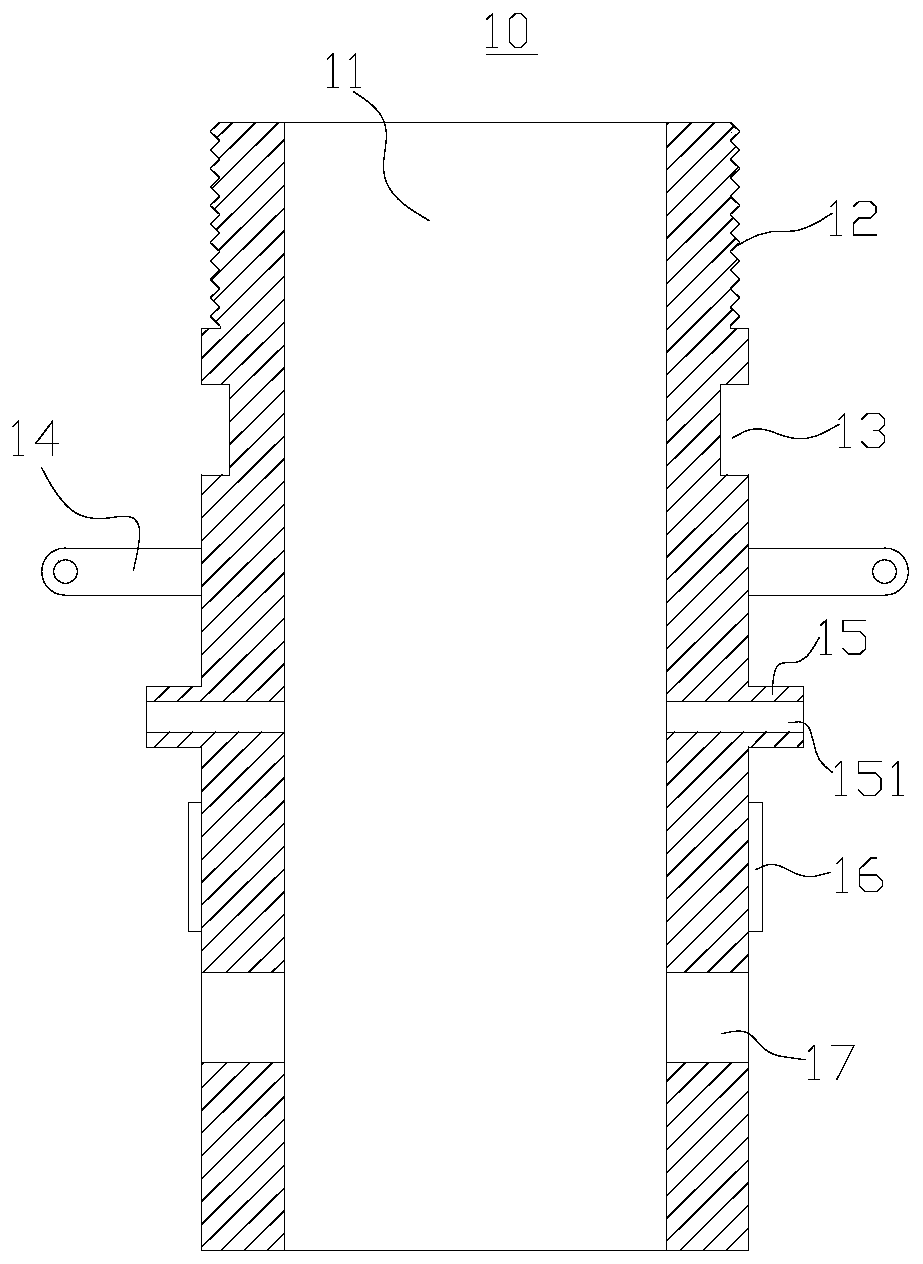
[0045] Among them, such as figure 2As shown, the central sleeve 10 is used to cooperate with the column 210. The central sleeve 10 is cylindrical and has a central hole 11. The shape of the central hole 11 is set according to the shape of the column 210, which can be circular, square, etc. The center sleeve 10 is sequentially provided with an external thread 12 , a sliding groove 13 , a hinge seat 14 , a protruding part 15 , a protruding line 16 and a socket 17 from top to bottom. The external thread 12 is located on the top of the center sleeve 10 . The chute 13 is opened along the tangential direction of the center sleeve 10 , and the chute 13 is a rectangular groove locate...

Embodiment 2

[0059] Such as Figure 8 As shown, the present embodiment provides a connection structure 200, including a column 210, a beam 220 and the building structure connection device in the above embodiment.

[0060] The center sleeve 10 is sleeved on the outside of the column 210 , and the locking member 60 locks the center sleeve 10 and the column 210 . In this embodiment, there are four beams 220, and the four beams 220 are respectively arranged in the receiving grooves 24 of the four first clamping bodies 20, and the first clamping part 21 and the second clamping part 23 are clamped to the width of the beam 220. On both sides in the direction, the base 22 and the actuator 51 are clamped on both sides of the beam 220 in the thickness direction.


PUM


Abstract

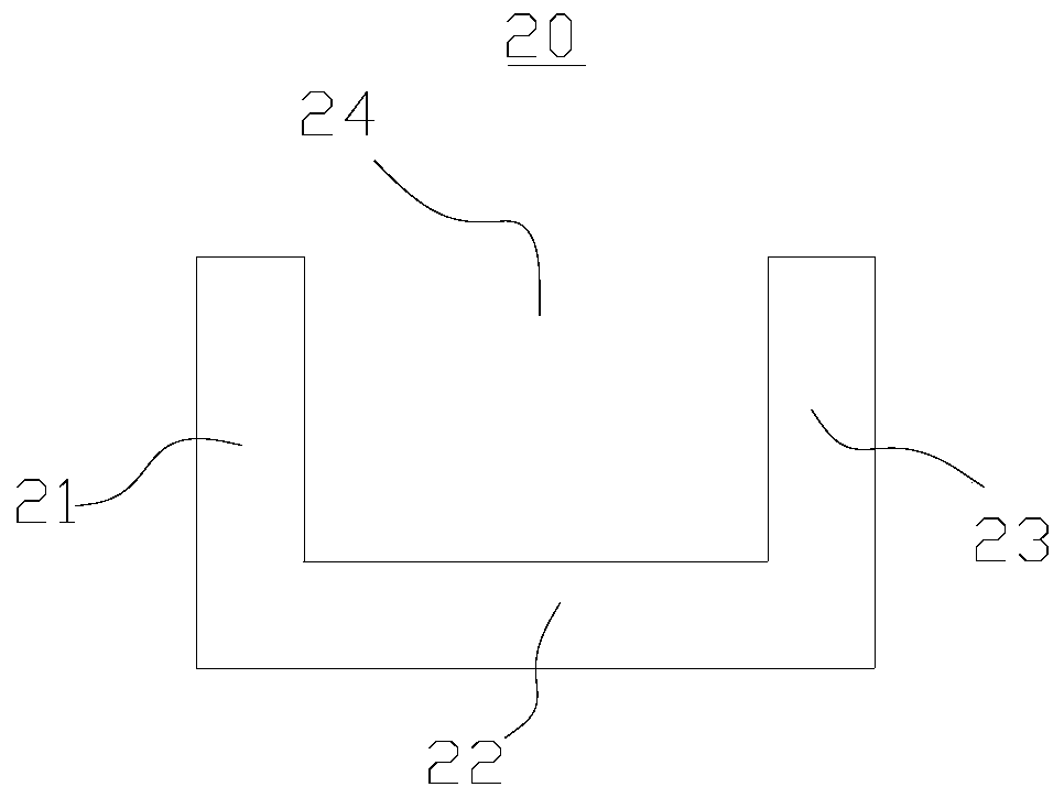
The invention provides a building steel structure connection device and a connection structure, which belong to the field of construction engineering. The building steel structure connecting device includes a center sleeve, a first clip body, a second clip body, a driving device and a clamping device. The first clamping body is fixed on the outer side of the central sleeve, and the first clamping body includes a base, a first clamping part and a second clamping part, and both the first clamping part and the second clamping part are connected to the base. The second clamping body is movably arranged on the outside of the center sleeve, and the second clamping body is provided with an extruding part. The driving device can drive the second clamping body to move towards the direction close to the first clamping body, so that the extrusion part presses the first clamping part and the second clamping part, so that the first clamping part and the second clamping part are mutually near. The clamping device includes an executive part, which is movably connected with the central sleeve, and the executive part has a clamping end, and the distance between the clamping end and the base is adjustable. The connection device can limit the swing of the beam relative to the column in two directions, and the beam and the column have good firmness after being connected through the connection device.

Description

technical field [0001] The invention relates to the field of construction engineering, in particular to a connection device and a connection structure for a building steel structure. Background technique [0002] At present, the application of steel structure buildings is very common. In steel structure buildings, the connection structure of columns and beams is very important, and it must be ensured to have sufficient firmness. In the prior art, the column and the beam are generally connected by connecting plates, and the firmness of the connection between the column and the beam is poor. Contents of the invention [0003] The object of the present invention is to provide a connection device for a building steel structure, so as to improve the problem of poor firmness after the connection between the column and the beam. [0004] The purpose of the present invention is to provide a connection structure to improve the problem of poor firmness after the column and the beam...

Claims


Application Information

Patent Timeline
Patent Type & Authority Patents(China)
IPC IPC(8): E04B1/24E04B1/58
CPCE04B1/2403E04B2001/2415
Inventor 王炳监
Owner 吉林省飞达杭萧建筑科技有限公司
Learn More