Improved power distribution cabinet device

A power distribution cabinet and improved technology, applied in substation/power distribution device shell, circuit device, emergency protection circuit device, etc. The effect of reducing the occupied space and the simple structure of the device

Inactive Publication Date: 2018-06-26
潘绍合
View PDF8 Cites 16 Cited by
  • Summary
  • Abstract
  • Description
  • Claims
  • Application Information

AI Technical Summary

Problems solved by technology

[0002] The power distribution cabinet is widely used in the field of power integration. It is mainly used to install electronic components and is an important part of power equipment. However, the traditional installation mode of the power distribution cabinet is complicated and time-consuming, which seriously reduces the installation efficiency. , which brings inconvenience to the use. At the same time, because the power distribution cabinets are generally installed outside, and the existing power distribution cabinets have weak protection, lightning accidents often occur, and there are great potential safety hazards.

Method used


Image

  • Improved power distribution cabinet device
  • Improved power distribution cabinet device
  • Improved power distribution cabinet device

Examples


Embodiment Construction

[0021] All features disclosed in this specification, or steps in all methods or processes disclosed, may be combined in any manner, except for mutually exclusive features and / or steps.

[0022] Any feature disclosed in this specification (including any appended claims, abstract and drawings), unless expressly stated otherwise, may be replaced by alternative features which are equivalent or serve a similar purpose. That is, unless expressly stated otherwise, each feature is one example only of a series of equivalent or similar features.

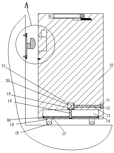
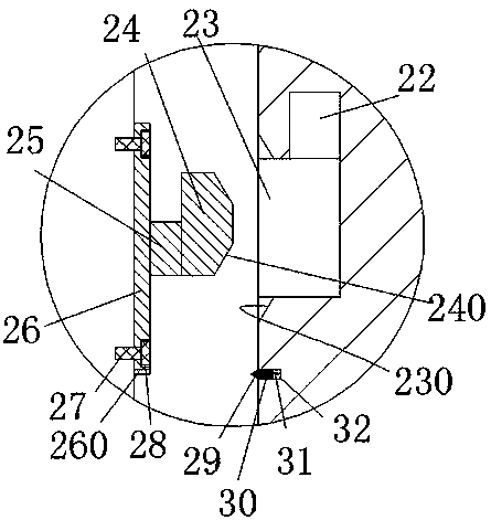
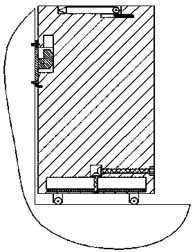
[0023] Such as Figure 1-5 As shown, an improved power distribution cabinet device of the device of the present invention includes a power distribution cabinet 10, a protective structure arranged in the power distribution cabinet 10, and a locking structure for fixing the power distribution cabinet 10. The locking structure includes an assembly plate 26, a fixed arm 25 fixed on the right end of the assembly plate 26, and a locking arm 24 fixe...


PUM


Abstract

The invention discloses an improved power distribution cabinet device. The improved power distribution cabinet device comprises a power distribution cabinet, a protection structure and a locking structure, wherein the protection structure is arranged in the power distribution cabinet, the locking structure is used for fixing the power distribution cabinet and comprises an assembly plate, a fixed connection arm and a locking arm, the fixed connection arm is fixedly arranged on a right end surface of the assembly plate, the locking arm is fixedly arranged at a right end of the fixed connection arm and extends upwards, first bevel surfaces are vertically and symmetrically arranged on a right end surface of the locking arm, installation grooves are vertically and symmetrically formed in the right end surface of the assembly plate and are provided with rightward ports, a communication groove is formed in a left end wall of each installation groove and communicates with an outer end, a spiral nail is arranged in the communication groove and is used for fixing the assembly plate on a wall, an insertion cavity is formed in a left end surface of the power distribution cabinet and is provided with a leftward port, a locking groove is formed in a right upper end of the insertion cavity, extends upwards and is matched with the locking arm, a push groove is further formed in a position, arranged below the locking groove, of a left end surface of the power distribution cabinet, a sliding arm is arranged in the push groove in a sliding way, and a drawing head is fixedly arranged at a leftend of the sliding arm.

Description

technical field [0001] The invention relates to the field of power equipment, in particular to an improved power distribution cabinet device. Background technique [0002] The power distribution cabinet is widely used in the field of power integration. It is mainly used to install electronic components and is an important part of power equipment. However, the traditional installation mode of the power distribution cabinet is complicated and time-consuming, which seriously reduces the installation efficiency. , which brings inconvenience to the use, and because the power distribution cabinets are generally installed outside, and the existing power distribution cabinets have weak protection, lightning accidents often occur, and there are great potential safety hazards. Contents of the invention [0003] Aiming at the deficiencies of the above technologies, the present invention proposes an improved power distribution cabinet device. [0004] An improved power distribution c...

Claims


Application Information

Patent Timeline
Patent Type & Authority Applications(China)
IPC IPC(8): H02B1/30H02H9/04
CPCH02B1/30H02B1/303H02H9/047
Inventor 潘绍合
Owner 潘绍合
Why Eureka
Try Eureka