Waste and abandoned bulb treatment equipment

A technology for processing equipment and light bulbs, which is applied in grain processing and other fields, and can solve the problems of low processing efficiency, time-consuming and labor-intensive problems

Inactive Publication Date: 2018-06-29
饶胜智
View PDF6 Cites 9 Cited by
  • Summary
  • Abstract
  • Description
  • Claims
  • Application Information

AI Technical Summary

Problems solved by technology

[0005] In order to overcome the time-consuming and labor-intensive and low-efficiency shortcomings of manual crushing of waste light bulbs, the technical problem to be solved by the present invention is to provide a waste Bulb Treatment Equipment

Method used


Image

  • Waste and abandoned bulb treatment equipment
  • Waste and abandoned bulb treatment equipment
  • Waste and abandoned bulb treatment equipment

Examples


Embodiment 1

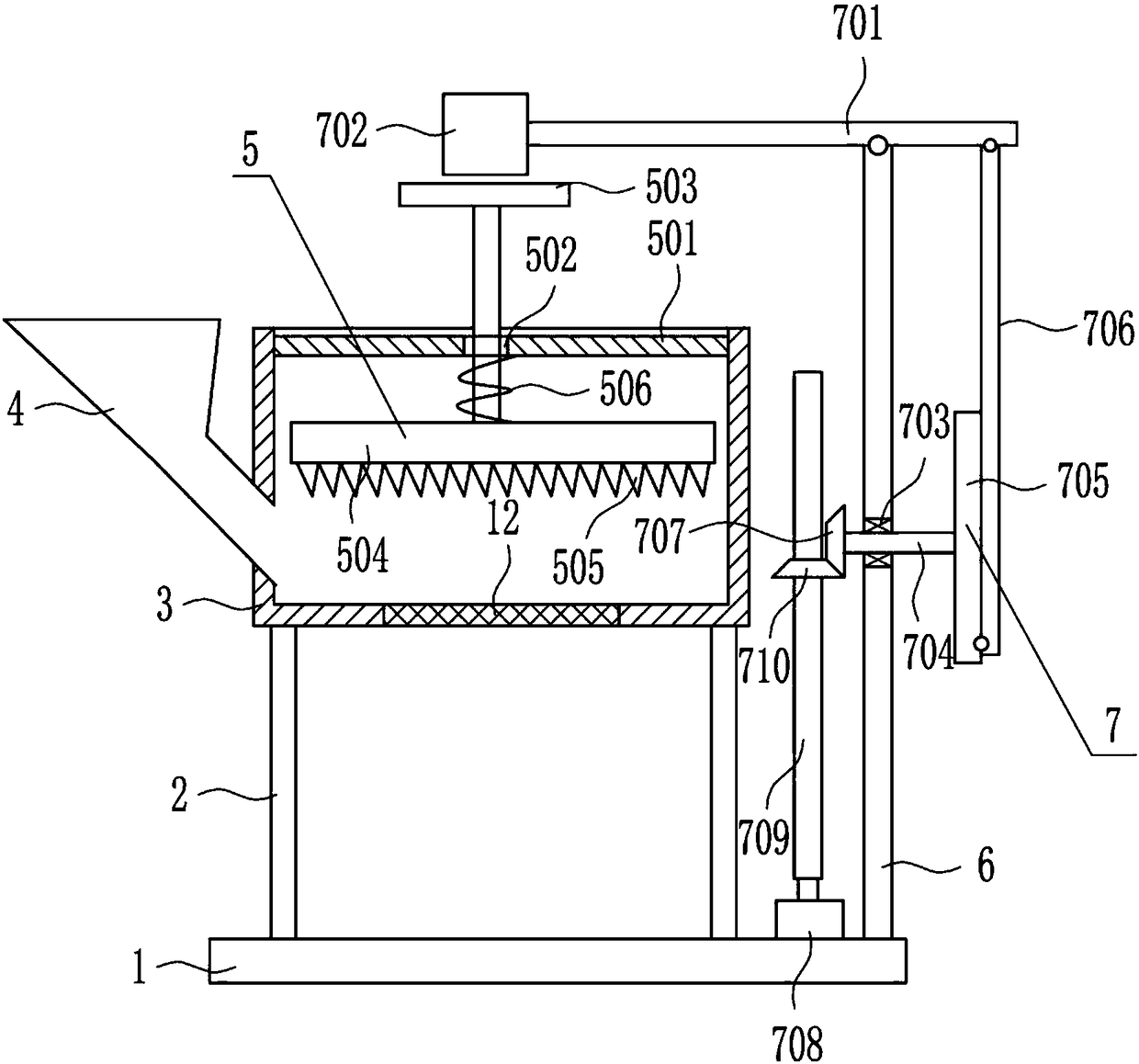
[0027] A waste light bulb treatment facility such as Figure 1-3 As shown, it includes a base 1, a pole 2, a processing box 3, a lower hopper 4, a crushing device 5, a support plate 6, a driving device 7 and a mesh plate 12, and the top of the base 1 is vertically connected with two poles by bolts 2. The two poles 2 are left and right symmetrical, and a treatment box 3 is connected between the tops of the two poles 2. The top of the treatment box 3 is open, and the lower part of the left side of the treatment box 3 is equipped with a lower hopper 4. Crushing device 5 is provided in processing box 3, and screen plate 12 is installed in the middle of the bottom of processing box 3, and base 1 top, processing box 3 right sides is vertically connected with support plate 6, and support plate 6 is provided with drive unit 7.

Embodiment 2

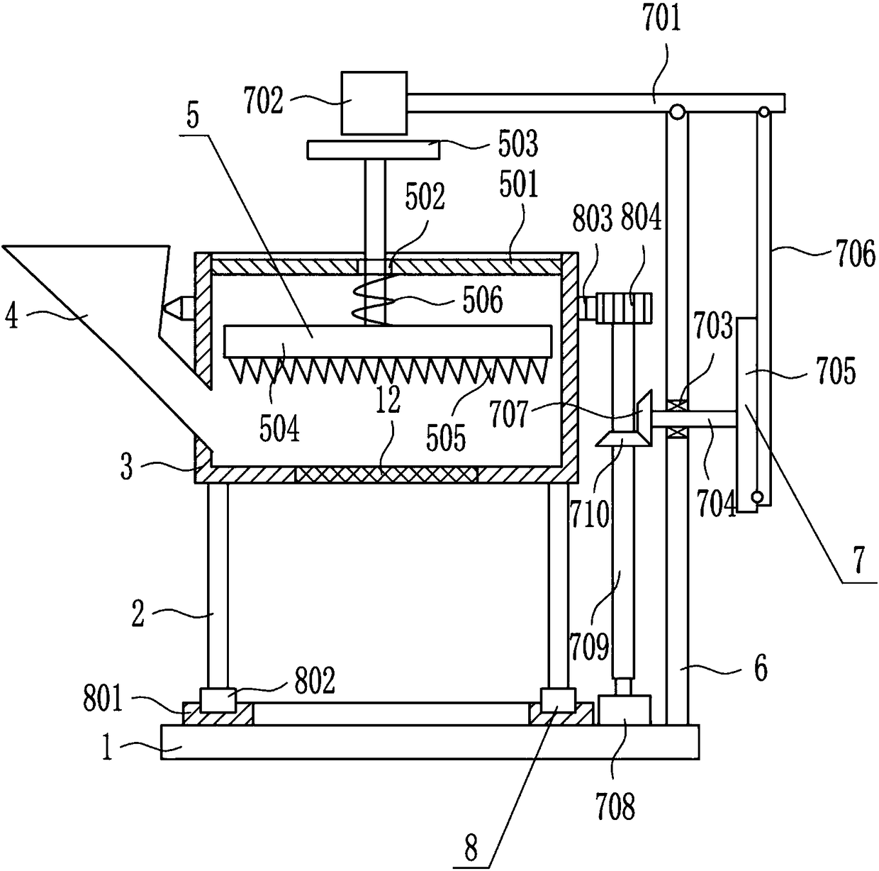
[0029] A waste light bulb treatment facility such as Figure 1-3 As shown, it includes a base 1, a pole 2, a processing box 3, a lower hopper 4, a crushing device 5, a support plate 6, a driving device 7 and a mesh plate 12, and the top of the base 1 is vertically connected with two poles by bolts 2. The two poles 2 are left and right symmetrical, and a treatment box 3 is connected between the tops of the two poles 2. The top of the treatment box 3 is open, and the lower part of the left side of the treatment box 3 is equipped with a lower hopper 4. Crushing device 5 is provided in processing box 3, and screen plate 12 is installed in the middle of the bottom of processing box 3, and base 1 top, processing box 3 right sides is vertically connected with support plate 6, and support plate 6 is provided with drive unit 7.

[0030] Crushing device 5 comprises connecting plate 501, T-shaped guide bar 503, crushing plate 504, crushing tooth 505 and spring 506, and connecting plate 5...

Embodiment 3

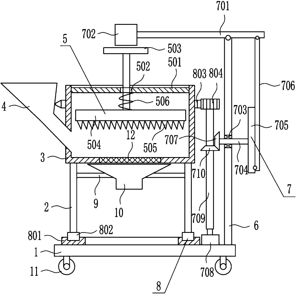
[0032] A waste light bulb treatment facility such as Figure 1-3As shown, it includes a base 1, a pole 2, a processing box 3, a lower hopper 4, a crushing device 5, a support plate 6, a driving device 7 and a mesh plate 12, and the top of the base 1 is vertically connected with two poles by bolts 2. The two poles 2 are left and right symmetrical, and a treatment box 3 is connected between the tops of the two poles 2. The top of the treatment box 3 is open, and the lower part of the left side of the treatment box 3 is equipped with a lower hopper 4. Crushing device 5 is provided in processing box 3, and screen plate 12 is installed in the middle of the bottom of processing box 3, and base 1 top, processing box 3 right sides is vertically connected with support plate 6, and support plate 6 is provided with drive unit 7.

[0033] Crushing device 5 comprises connecting plate 501, T-shaped guide bar 503, crushing plate 504, crushing tooth 505 and spring 506, and connecting plate 50...


PUM


Abstract

The invention relates to bulb treatment equipment, in particular to waste and abandoned bulb treatment equipment, and aims at providing the waste and abandoned bulb treatment equipment with the advantages that the time and the labor are saved; the treatment efficiency can be improved; the use is convenient; the operation is simple. In order to solve the technical problems, the invention provides the waste and abandoned bulb treatment equipment, which comprises a base, support rods, a treatment box, a discharging hopper, a crushing device, a support plate and the like, wherein the top of the base is vertically connected with two support rods through screw bolts; the two support rods are symmetrical at the left side and the right side; a treatment box is connected between the top ends of thetwo support rods; the top of the treatment box is in an open opening type arrangement; the discharging hoper is arranged at the lower part of the left side surface of the treatment box; the crushingdevice is arranged in the treatment box. The crushing device can be driven by the driving device to perform crushing treatment on the waste and abandoned bulb, so that the effects that the time and the labor are saved; the treatment efficiency can be improved; the use is convenient; the operation is simple.

Description

technical field [0001] The invention relates to a light bulb processing device, in particular to a waste light bulb processing device. Background technique [0002] Luminaires refer to appliances that can transmit light, distribute and change the light distribution of the light source, including all parts required to fix and protect the light source except the light source, as well as the necessary line accessories for connection to the power supply. [0003] A large number of waste light bulbs are produced every year, which will occupy a large area of ​​land. In order to reduce the area occupied by waste light bulbs, waste light bulbs need to be crushed. At present, waste light bulbs are generally broken manually, which is time-consuming and laborious. The efficiency is low, so there is an urgent need to develop a waste light bulb processing equipment that can save time and effort, improve processing efficiency, be easy to use, and be simple to operate. Contents of the in...

Claims


Application Information

Patent Timeline
Patent Type & Authority Applications(China)
IPC IPC(8): B02C1/14B02C23/16
CPCB02C1/14B02C23/16B02C2201/06
Inventor 饶胜智陈星李蓓
Owner 饶胜智
Why Eureka
Try Eureka