Circular disc positioning assembly

A technology for positioning components and discs, used in metal processing, metal processing equipment, manufacturing tools, etc., can solve the problems of low degree of automation, increase production costs, long labor time, etc., achieve high degree of automation, improve quality, and solve positioning problems troublesome effect

Pending Publication Date: 2017-08-18
苏州麦克韦尔自动化设备有限公司
View PDF0 Cites 2 Cited by
  • Summary
  • Abstract
  • Description
  • Claims
  • Application Information

AI Technical Summary

Problems solved by technology

[0002] In the prior art, it is necessary to drop the needle valve into the disc hole. Due to the low degree of automation, it is manually adjusted and positioned, resulting in a decline in quality, high labor intensity, and long labor time; it further increases production costs.

Method used


Image

  • Circular disc positioning assembly
  • Circular disc positioning assembly

Examples


Embodiment Construction

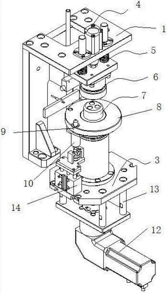
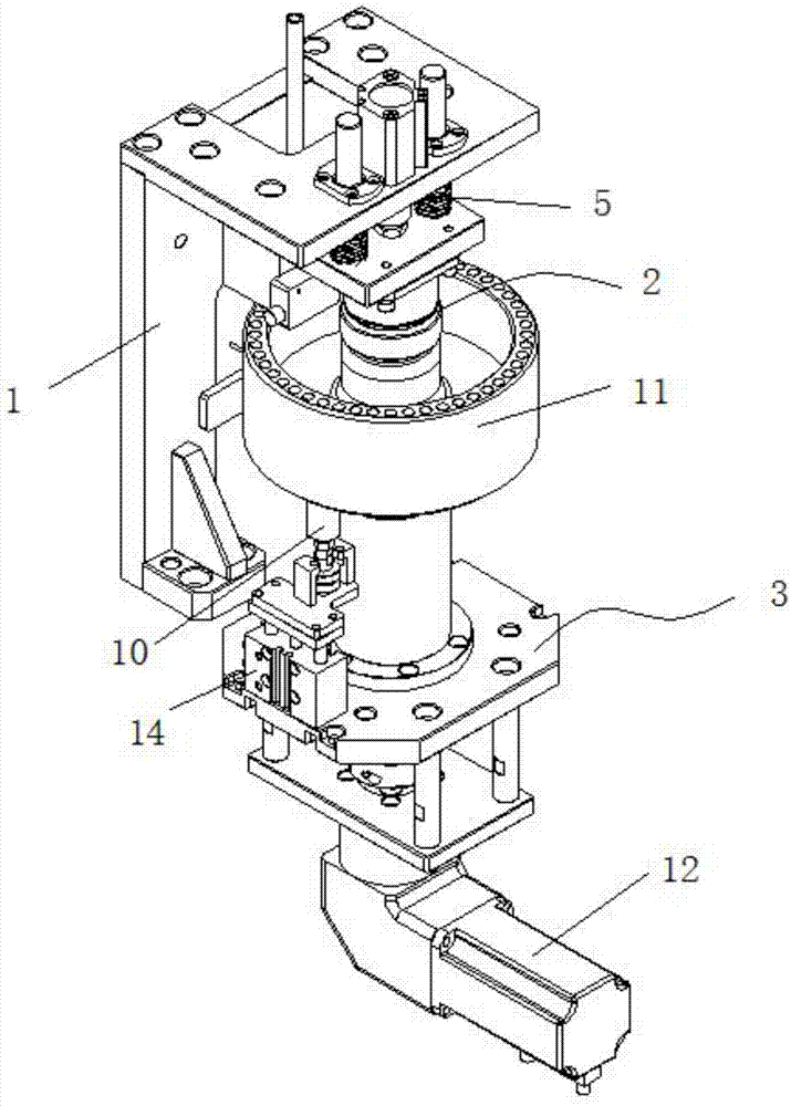
[0013] See figure 1 and figure 2 A disc positioning assembly shown has a fixed bracket 1, a pressing mechanism 2, and a jacking mechanism 3. The pressing mechanism 2 is fixed on the fixing bracket 1, and the jacking mechanism 3 is arranged on the At the bottom, the pressing mechanism 2 includes a cylinder 4, a spring assembly 5, and a central shaft 6. The positioning plate 8 has a pin hole 9, and the pin 10 of the jacking part 3 is mated with the pin hole 9. The positioning shaft 7 is socketed with the positioning disc 8, and the two are rotated clockwise through a one-way bearing. The fixing bracket 1 is provided with a sensor, and the sensor is arranged above the positioning plate 8 for sensing the position of the pin hole 9 . Jacking part 3 comprises servomotor 12, is positioned at described servomotor 12 top and is provided with support 13, and one end of described support 13 has ejector 14, and described ejector 14 is provided with pin 10.

[0014] Its working process...


PUM


Abstract

The invention discloses a disk positioning assembly, which has a fixing bracket, a pressing mechanism and a jacking mechanism. The pressing mechanism is fixed on the fixing bracket, and the jacking mechanism is arranged at the bottom of the pressing mechanism. The tightening mechanism includes a cylinder, a spring assembly, a central shaft, and a positioning shaft. The positioning plate is provided with a pin hole, and the pin of the lifting component is matched and connected with the pin hole. The technical solution of the present invention has a high degree of automation. The positioning plate and the pin are positioned, which quickly solves the shortcomings of troublesome positioning and complicated operation. This design scheme not only improves work efficiency, but also has a high degree of automation, which further reduces production costs and improves product quality. It can be quickly dropped into the hole of the disc without error.

Description

technical field [0001] The invention relates to the technical field of positioning components of automation equipment, in particular to a disk positioning component. Background technique [0002] In the prior art, the needle valve needs to be dropped into the disc hole. Due to the low degree of automation, manual adjustment and positioning are all carried out, resulting in a decrease in quality, high labor intensity, and long labor time; further increasing the production cost. Contents of the invention [0003] The object of the present invention is to solve the above-mentioned problems and provide a disc positioning assembly with simple structure and high degree of automation. [0004] The object of the present invention is achieved in the following manner, a disc positioning assembly has a fixed bracket, a pressing mechanism, and a jacking mechanism, the pressing mechanism is fixed on the fixing bracket, and the jacking mechanism is arranged on the pressing The bottom o...

Claims


Application Information

Patent Timeline
Patent Type & Authority Applications(China)
IPC IPC(8): B23P19/00
CPCB23P19/002
Inventor 刘泽波
Owner 苏州麦克韦尔自动化设备有限公司
Why Eureka
Try Eureka