
Improved glue sprayer and glue spraying waste gas treatment method applying improved glue sprayer

A glue spraying machine and improved technology, applied in spray booths, spraying devices, etc., can solve the problems that operators are easy to catch cold, difficult to inhale glue mist, physical discomfort, etc., and achieve improved comfort, compact structure, and broad market prospects. Effect

Pending Publication Date: 2018-06-29
福建省统一环保科技有限公司
View PDF1 Cites 0 Cited by
  • Summary
  • Abstract
  • Description
  • Claims
  • Application Information

AI Technical Summary

Problems solved by technology

The glue mist purification treatment structure of this glue sprayer has the following disadvantages: (1) The glue mist will still drift upward; (2) It is difficult to inhale the glue mist near the periphery of the mesh plate
In addition, the air outlet of the exhaust fan is located at the lower part of the machine base, and the air blows to the feet, and the operator is easy to catch cold and feel uncomfortable.

Method used


Image

  • Improved glue sprayer and glue spraying waste gas treatment method applying improved glue sprayer
  • Improved glue sprayer and glue spraying waste gas treatment method applying improved glue sprayer
  • Improved glue sprayer and glue spraying waste gas treatment method applying improved glue sprayer

Examples


Embodiment Construction

[0026] In order to make the above-mentioned features and advantages of the present invention more comprehensible, the following specific embodiments will be described in detail with reference to the accompanying drawings.

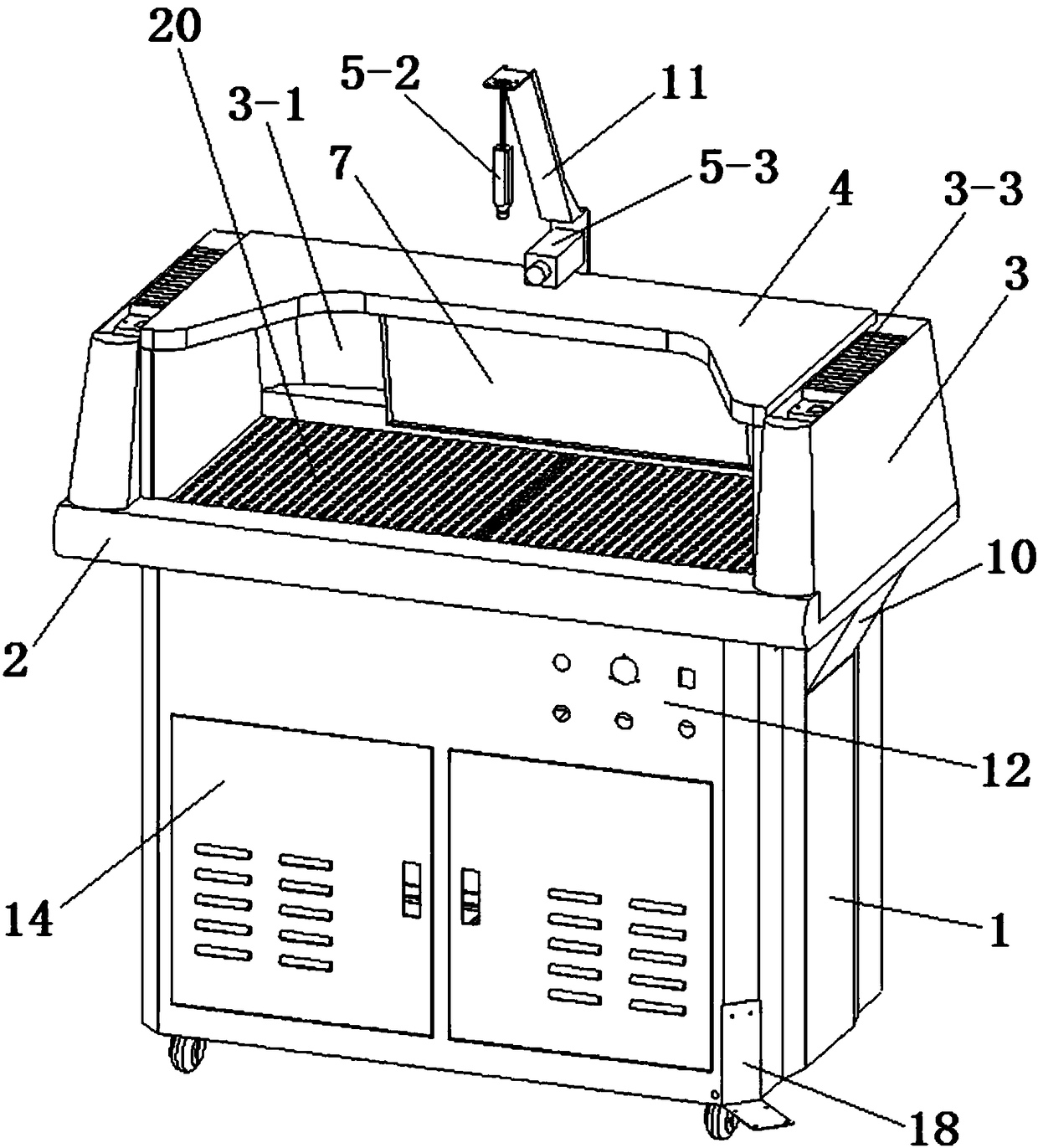
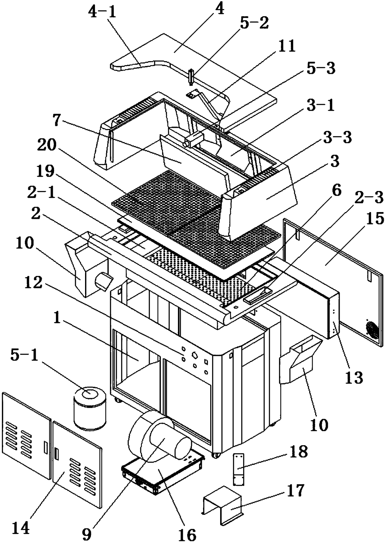
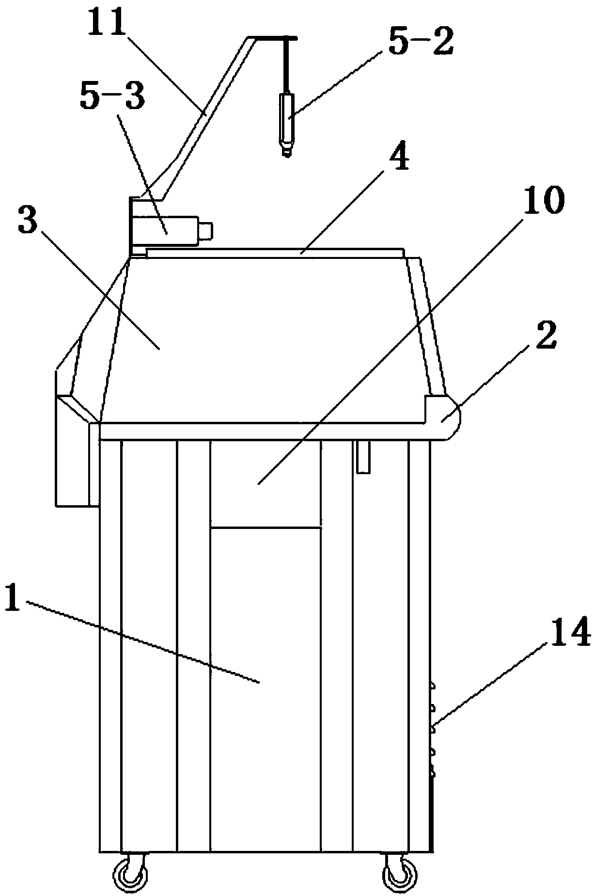
[0027] Such as Figure 1~10 As shown, an improved glue spraying machine includes a chassis 1, an operating platform 2, a diversion cover body 3, a top cover plate 4, a glue spraying device 5 and a filtering device 6, and the operating platform 2 is installed on the top of the chassis 1 , the diversion cover body 3 is installed on the operation platform 2 and surrounds the left, right and rear sides of the operation platform 2, the top cover plate 4 is installed on the top of the diversion cover body 3, and the top cover plate 4 The front end is provided with an avoidance gap 4-1 which is convenient for glue spraying operation, the front side of the middle part of the diversion cover body 3 is provided with an exhaust gas inlet 3-1, and the lower front side ...


PUM


Abstract

The invention discloses an improved glue sprayer and a glue spraying waste gas treatment method applying the improved glue sprayer. The improved glue sprayer comprises a case, an operation platform, aflow guiding cover body and a top cover plate. The flow guiding cover body surrounds the left side, the right side and the back side of the operation platform; the top cover plate is arranged on thetop part of the flow guiding cover body; a waste gas inlet is formed in the front side of the middle of the flow guiding cover body; a flow guiding plate is arranged in the middle of the waste gas inlet; a waste gas outlet is formed in the front side of the lower part of the flow guiding cover body; exhaust channels are arranged at the left end part and the right end part of the flow guiding coverbody; a filter cavity is arranged in the center of the operation platform; a seal cover plate is arranged on an opening of the upper end of the filter cavity; a gas inlet communicating with the wastegas is formed in a rear side wall of the filter cavity; a gas outlet hopper is arranged on an opening of the lower end of the filter cavity; an outlet of the gas outlet hopper is connected with inlets of two exhaust manifolds through an induced draft fan; and outlets of the two exhaust manifolds communicate with the two exhaust channels. The improved glue sprayer is ingenious in design, compact in structure and good in use effect.

Description

technical field [0001] The invention relates to the technical field of glue spraying machines, in particular to an improved glue spraying machine and a glue spraying waste gas treatment method using the glue spraying machine. Background technique [0002] Chinese utility model patent announcement number CN206731371U discloses a water-based glue spraying machine, which includes a machine base, a glue bucket, a control device, a glue spray gun, and a filter and adsorption device. Structure, the air inlet of the filter and adsorption device faces upward, and the glue mist above the mesh plate is directly sucked down by the exhaust fan. The glue mist purification treatment structure of this glue sprayer has the following disadvantages: (1) The glue mist will still drift upward; (2) It is difficult to inhale the glue mist near the periphery of the mesh plate. In addition, the air outlet of the exhaust fan is located at the bottom of the machine base, and the air is blown to the ...

Claims


Application Information

Patent Timeline
IPC IPC(8): B05B13/00B05B15/80B05B14/43B05B16/60
CPCB05B13/00
Inventor 邓宋明张国华
Owner 福建省统一环保科技有限公司
Learn More