Paintbrush cleaning machine

A technology for cleaning machines and brushes, applied in the field of cleaning machines, can solve the problems of slow cleaning speed, damage, damage to the brushes of the brushes, etc., and achieves the effect of fast cleaning speed and less damage.

Active Publication Date: 2018-06-29
李琴
View PDF2 Cites 0 Cited by
  • Summary
  • Abstract
  • Description
  • Claims
  • Application Information

AI Technical Summary

Problems solved by technology

[0005] In order to overcome the shortcomings of slow cleaning speed and easy damage to the brush of the paintbrush when cleaning the paintbrush manually, the technical problem to be solved by the present invention is to provide a brush that has a fast cleaning speed and is not easy to remove the brush of the paintbrush when cleaning. Brush Damaged Paintbrush Washing Machine

Method used


Image

  • Paintbrush cleaning machine
  • Paintbrush cleaning machine
  • Paintbrush cleaning machine

Examples


Embodiment 1

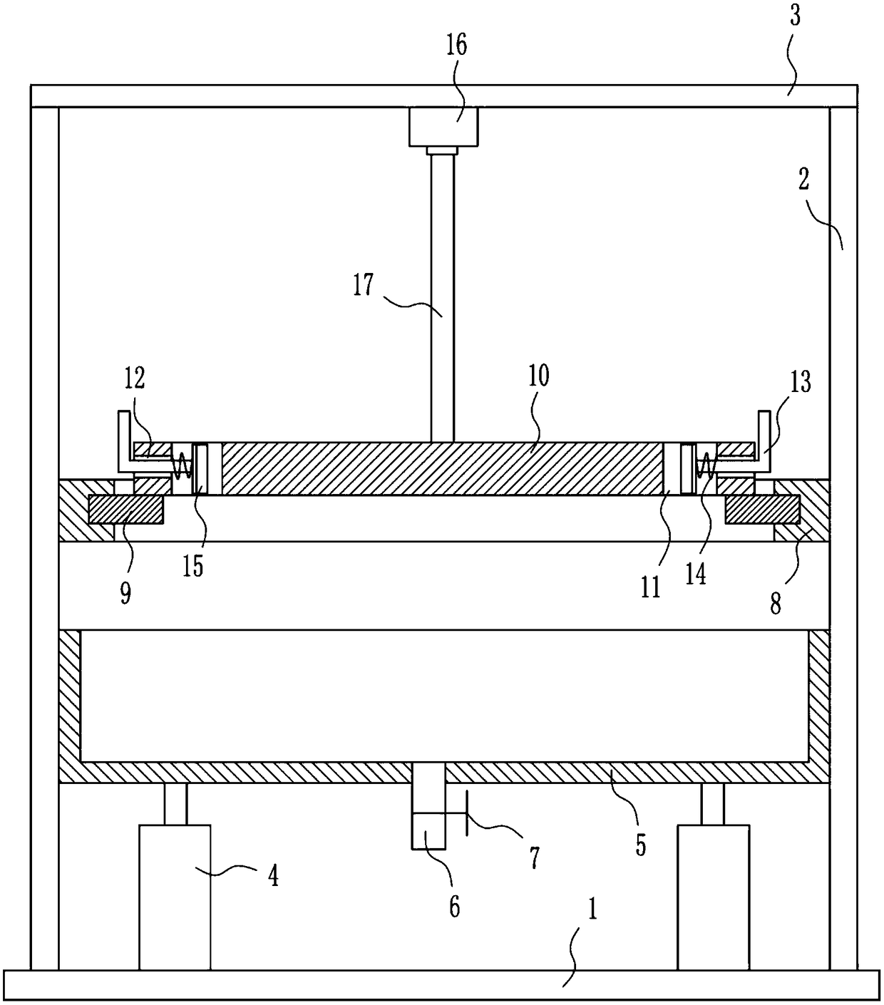
[0021] A brush cleaning machine, such as Figure 1-3 As shown, it includes a bottom plate 1, a vertical plate 2, a top plate 3, a cylinder 4, a frame body 5, a drain pipe 6, a first valve 7, an annular slide rail 8, an annular slider 9, a disc 10, an L-shaped tie rod 13, Spring 14, curved splint 15, motor 16 and rotating shaft 17, bottom plate 1 top, left and right sides are symmetrically equipped with cylinder 4, and cylinder 4 is vertically arranged, and frame body 5 is installed between the telescoping rods of left and right sides cylinder 4 , the middle of the bottom of the frame body 5 is connected with a drain pipe 6, the drain pipe 6 communicates with the inside of the frame body 5, the drain pipe 6 is provided with a first valve 7, and the left and right sides of the top of the bottom plate 1 are symmetrically installed with vertical boards 2 and vertical boards 2. Located on the left and right sides of the cylinder 4, a top plate 3 is installed between the tops of the...

Embodiment 2

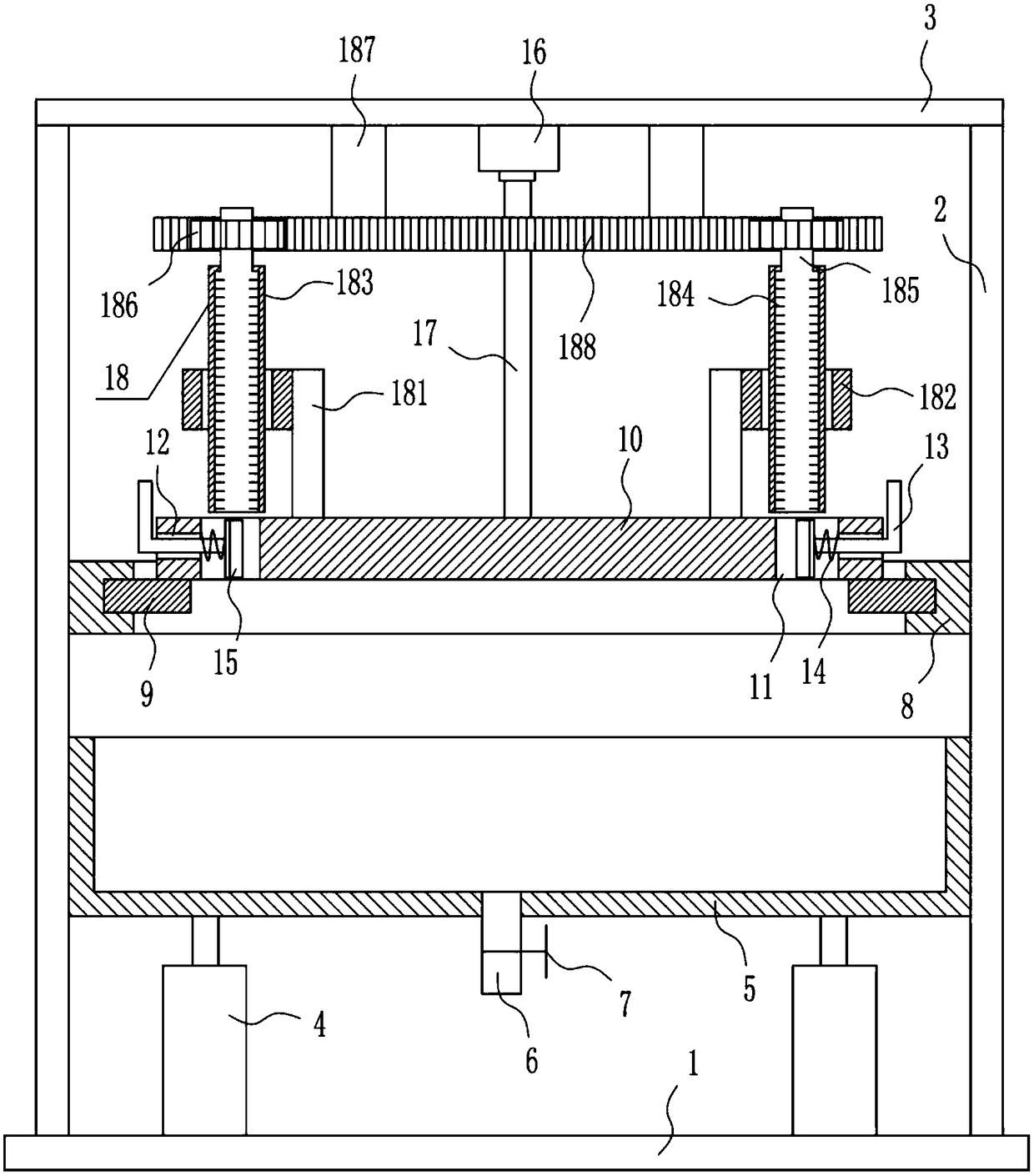
[0023] A brush cleaning machine, such as Figure 1-3 As shown, it includes a bottom plate 1, a vertical plate 2, a top plate 3, a cylinder 4, a frame body 5, a drain pipe 6, a first valve 7, an annular slide rail 8, an annular slider 9, a disc 10, an L-shaped tie rod 13, Spring 14, curved splint 15, motor 16 and rotating shaft 17, bottom plate 1 top, left and right sides are symmetrically equipped with cylinder 4, and cylinder 4 is vertically arranged, and frame body 5 is installed between the telescoping rods of left and right sides cylinder 4 , the middle of the bottom of the frame body 5 is connected with a drain pipe 6, the drain pipe 6 communicates with the inside of the frame body 5, the drain pipe 6 is provided with a first valve 7, and the left and right sides of the top of the bottom plate 1 are symmetrically installed with vertical boards 2 and vertical boards 2. Located on the left and right sides of the cylinder 4, a top plate 3 is installed between the tops of the...

Embodiment 3

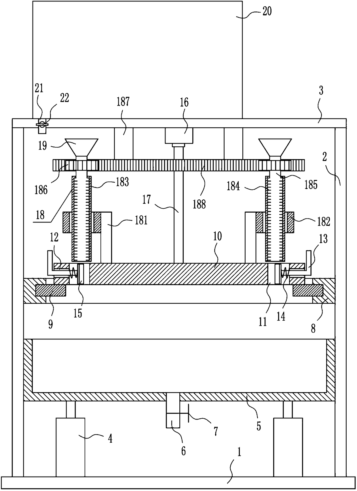
[0026] A brush cleaning machine, such as Figure 1-3 As shown, it includes a bottom plate 1, a vertical plate 2, a top plate 3, a cylinder 4, a frame body 5, a drain pipe 6, a first valve 7, an annular slide rail 8, an annular slider 9, a disc 10, an L-shaped tie rod 13, Spring 14, curved splint 15, motor 16 and rotating shaft 17, bottom plate 1 top, left and right sides are symmetrically equipped with cylinder 4, and cylinder 4 is vertically arranged, and frame body 5 is installed between the telescoping rods of left and right sides cylinder 4 , the middle of the bottom of the frame body 5 is connected with a drain pipe 6, the drain pipe 6 communicates with the inside of the frame body 5, the drain pipe 6 is provided with a first valve 7, and the left and right sides of the top of the bottom plate 1 are symmetrically installed with vertical boards 2 and vertical boards 2. Located on the left and right sides of the cylinder 4, a top plate 3 is installed between the tops of the v...


PUM


Abstract

The invention relates to a cleaning machine, in particular to a paintbrush cleaning machine. The paintbrush cleaning machine is high in cleaning speed, and brushes of paintbrushes cannot be easily damaged by the paintbrush cleaning machine during cleaning. The paintbrush cleaning machine comprises a bottom plate, vertical plates, a top plate, air cylinders, a frame, a drain pipe, a first valve, anannular slide rail, an annular slider, a disc, an L-shaped draw bar, a spring, an arc-shaped clamp plate and the like. The air cylinders are symmetrically mounted on the left side and the right sideof the top of the bottom plate and are vertically arranged, the frame is mounted between telescopic rods of the air cylinders on the left side and the right side of the top of the bottom plate, the drain pipe is connected with the middle of the bottom of the frame and is communicated with the inside of the frame, and the first valve is arranged on the drain pipe. The paintbrush cleaning machine has the advantages that the upper portions of the paintbrushes can be scrubbed by a scrubbing device, accordingly, the paintbrushes can be thoroughly cleaned by the paintbrush cleaning machine, the paintbrush cleaning machine is high in cleaning speed, and the brushes of the paintbrushes cannot be easily damaged by the paintbrush cleaning machine during cleaning.

Description

technical field [0001] The invention relates to a cleaning machine, in particular to a brush cleaning machine. Background technique [0002] Fine Arts: one of the categories of art. Use certain material materials, such as color, paper, canvas, soil, stone, wood, metal, wood, etc., to create a visible plane or three-dimensional visual image, to reflect nature and social life, and to express an artist's ideas and feelings. an artistic activity. Also called plastic arts, visual arts. It mainly includes painting, sculpture, arts and crafts, architectural art, etc. [0003] In art painting, brushes are used for painting, and there will be residual pigment after the brushes are used, and the brushes need to be cleaned. When cleaning the brushes manually, the cleaning speed is slow, and the brushes of the brushes are easy to be damaged during cleaning. Therefore, it is badly in need of developing a kind of cleaning speed fast, the paintbrush cleaning machine that is not easy to...

Claims


Application Information

Patent Timeline
Patent Type & Authority Applications(China)
IPC IPC(8): B44D3/00B43K13/02
CPCB43K13/02B44D3/00
Inventor 蔡樟鹏肖盟程国艳
Owner 李琴
Why Eureka
Try Eureka