Water dispenser with key
A water dispenser and key technology, which is applied to beverage preparation devices, devices for controlling liquid flow, and liquid distribution, etc., can solve the problems of cumbersome operation, inability to output hot water, and difficulty in completely eliminating the danger of young children taking hot water, etc. The effect of preventing scalding accidents
- Summary
- Abstract
- Description
- Claims
- Application Information
AI Technical Summary
Problems solved by technology
Method used
Image

Examples
Embodiment Construction
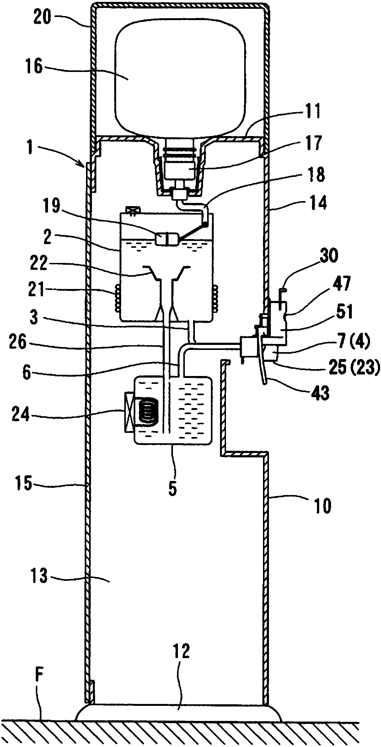
[0056] figure 1 A keyed water dispenser according to an embodiment of the present invention is shown in . The water dispenser has: a casing 1, which is placed on the floor surface F; a cold water tank 2, which is accommodated in the inside of the casing 1; The external output of body 1; the cold water output valve 4, which opens and closes the cold water output channel 3; the hot water tank 5, which is accommodated in the inside of the housing 1; the hot water output channel 6, which is used The high-temperature drinking water is output to the outside of the casing 1; and the hot water output valve 7 is used to open and close the hot water output channel 6.
[0057] The housing 1 has: a cylindrical portion 10 extending in the vertical direction; a top plate 11 provided to close the upper end of the cylindrical portion 10 ; and a bottom plate 12 provided to close the lower end of the cylindrical portion 10 . The cylindrical part 10 is comprised including: a pair of left and r...
PUM
 Abstract
Description
Claims
Application Information
PatSnap Eureka turns technology decisions into work you can execute. Powered by our Innovation Knowledge Graph, it runs expert workflows across engineering, life sciences, materials and intellectual property. Get your review-ready output in minutes.


