Bending machining device applied to strip parts

A processing device and parts technology, applied in the field of bending processing devices, can solve problems such as the influence of bending angle, the influence of processing accuracy, and the jumping of strip parts

Pending Publication Date: 2018-07-06
苏州冬宝光电科技有限公司
View PDF6 Cites 0 Cited by
  • Summary
  • Abstract
  • Description
  • Claims
  • Application Information

AI Technical Summary

Problems solved by technology

The traditional bending of bar-shaped parts is to position the bar-shaped parts, and the cylinder drives the push rod to directly bend. However, when bending, the strip-shaped parts often jump due to excessive driving force, which is easy to bend. Causes an impact on the bending angle, thereby affecting the overall machining accuracy

Method used


Image

  • Bending machining device applied to strip parts
  • Bending machining device applied to strip parts

Examples


Embodiment 1

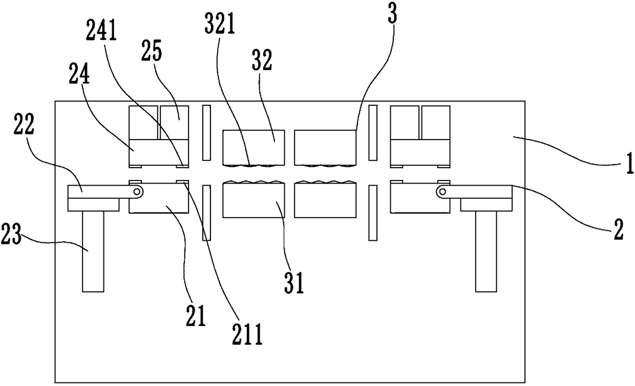
[0018] see figure 1 , the figure shows a bending processing device applied to strip-shaped parts provided by Embodiment 1 of the present invention, which includes a base 1, and two bending mechanisms arranged symmetrically are installed on the base 1, and the bending mechanism includes a bending Part 2 and guide part 3, the bending part 2 includes a fixed first positioning block 21, one side of the first positioning block 21 is hinged with a push rod 22, the push rod 22 is connected to the first driving part 23, and the base 1 is movably installed There is a second positioning block 24 opposite to the first positioning block 21, and the second positioning block 24 is connected to the second driving part 25. The guide part 3 includes a first guiding block 31 and a second guiding block 32 arranged oppositely. The first guiding block 31 Arranged in a straight line with the first positioning block 21 , the second guide block 32 is arranged in a straight line with the second positi...

Embodiment 2

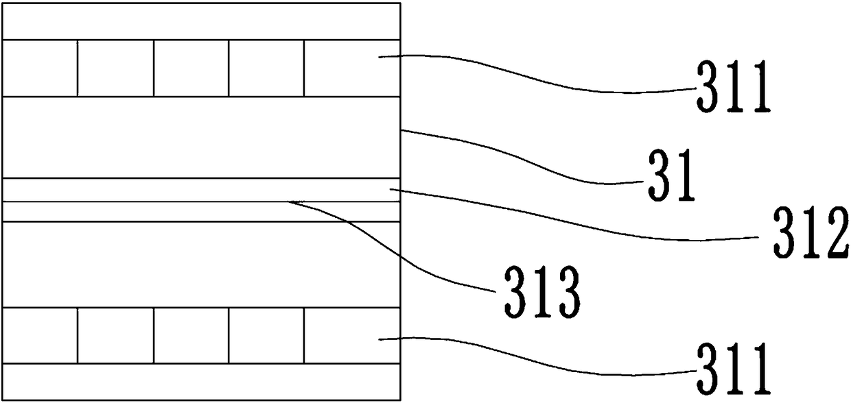
[0021] see figure 1 , the figure shows a bending processing device applied to bar-shaped parts provided by Embodiment 2 of the present invention. This embodiment further makes the following technical solutions as improvements on the basis of the above embodiments: The shape surface includes two racks 311 oppositely arranged; a through groove 312 opened on the side of the first guide block 31 is arranged between the two racks 311 ; a boss 313 is arranged at the bottom of the through groove 312 . Through the arrangement of the above structure, accurate guidance in the vertical direction can be formed, and the adsorption force to the product can be improved in the vertical direction.

Embodiment 3

[0023] see figure 1 , the figure shows a bending processing device applied to bar-shaped parts provided by Embodiment 3 of the present invention. On the basis of the above embodiments, this embodiment further makes the following technical solutions as improvements: the first The side surfaces of the two guide blocks 32 are provided with wave surfaces 321 . Through the setting of the above structure, the beating of the product can be further reduced.


PUM


Abstract

The invention provides a bending machining device applied to strip parts. The device comprises a base, two bending mechanisms which are symmetrically arranged are arranged on the base, each bending mechanism comprises a bending comment and a guide component, each bending component comprises a first positioning block fixedly arranged, a push rod is hinged to one side of each first positioning block, the push rods are connected with first drive components, second positioning blocks opposite to the first positioning blocks are movably arranged on the base, and are connected with second drive components, each guide component comprises a first guide block and a second guide block which are oppositely arranged, each first guide block and the corresponding first positioning block are linearly arranged, each second guide block and the corresponding second positioning block are linearly arranged, and a toothed face is arranged on the side face of each first guide block. Compared with the priorart, jumping of products can be effectively overcome, the influence on the bending angle can be reduced, and bending precision can be improved.

Description

technical field [0001] The invention relates to a bending processing device, in particular to a bending processing device applied to strip parts. Background technique [0002] For the processing of products such as display panels, the frames on them are usually formed by bending strip parts. The traditional bending of bar-shaped parts is to position the bar-shaped parts, and the cylinder drives the push rod to directly bend. However, when bending, the strip-shaped parts often jump due to excessive driving force, which is easy to bend. It will affect the bending angle, thereby affecting the overall processing accuracy. Contents of the invention [0003] In view of this, the present invention provides a bending processing device applied to bar-shaped parts that can improve processing accuracy. [0004] To this end, the present invention provides a bending processing device applied to bar-shaped parts, which includes a base on which two symmetrically arranged bending mechan...

Claims


Application Information

Patent Timeline
Patent Type & Authority Applications(China)
IPC IPC(8): B21D7/022
CPCB21D7/022
Inventor 丁祥松
Owner 苏州冬宝光电科技有限公司
Why Eureka
Try Eureka