
Flocking roller

A flocking roller and flocking technology, applied in the field of flocking rollers, can solve the problems of unsustainable elasticity, loss of elasticity and durability, and achieve the effect of prolonging the service life and working stably

Inactive Publication Date: 2009-12-02
SHENZHEN FANCY CREATION INDAL
View PDF0 Cites 7 Cited by
  • Summary
  • Abstract
  • Description
  • Claims
  • Application Information

AI Technical Summary

Problems solved by technology

However, in order to ensure that the flocking layer and the matching roller form a matching abutment during work to meet the needs of the operation, the flocking fiber must be bent and deformed by the matching roller in the initial state (when not working) to generate restoring elasticity to provide the work. The force of the action; the elasticity of the fiber is difficult to last. As the use time increases, the fiber itself of the flocking layer has a deformation that is difficult to recover, loses elasticity, and can no longer produce force, which makes it difficult or even impossible for the fiber and the matching roller to A matching abutment is formed, which affects the normal operation of the flocking roller, for example, the amount of toner transport is not ideal or the cleaning of the toner cartridge is not satisfactory
In addition, if the mutual position setting between the flocking roller and the matching roller is unreasonable, at the beginning, the fiber deformation is too large and the torque of matching with the matching roller is too large, which will also cause the gap between the flocking roller and the other roller. inter-injury
In short, the defect of the flocking roller is that the elasticity is not durable and durable, and the product quality is difficult to meet the ideal requirements.
[0005] In summary, the structure of the functional rollers used in the existing office equipment has deficiencies and needs to be improved

Method used


Image

  • Flocking roller

Examples


Embodiment Construction

[0034] For further elaborating the technical means and effects that the present invention adopts to achieve the predetermined purpose, please refer to the following detailed description and accompanying drawings of the present invention. It should be understood that the drawings and embodiments are only provided for reference and description, and are not intended to limit the present invention.

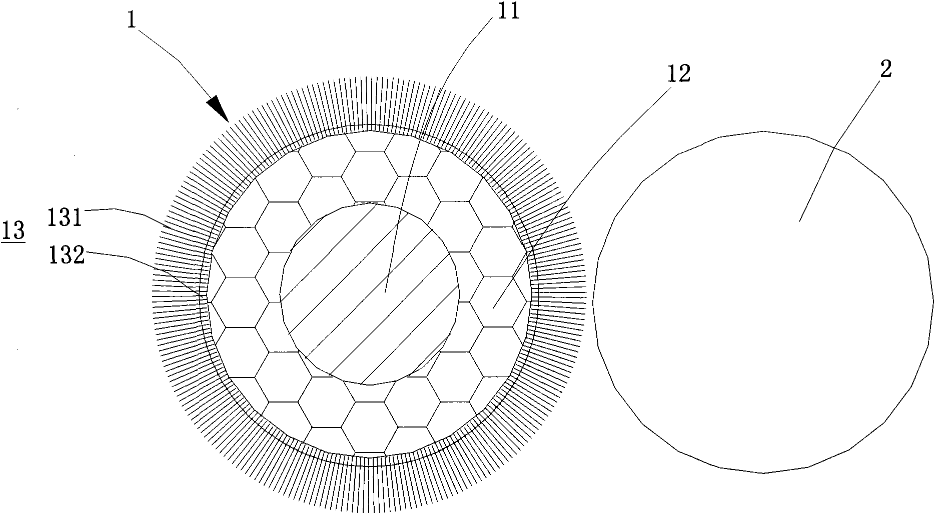
[0035] Such as figure 1 As shown, the flocking roller 1 of the present invention abuts against the mating roller 2 in a matched manner, and the mating roller 2 can be a flocking roller or other roller shafts, which are only schematically shown in the figure.

[0036] The flocking roller 1 includes a roller core 11 and a composite working layer that forms a matching abutment with the mating roller 2;

[0037] The roller core 11 can be made of metal materials or resin plastics, and its shape can be cylindrical as shown in the figure. In other embodiments, the roller core 11 can also be...


PUM

PropertyMeasurementUnit
Thicknessaaaaaaaaaa
Thicknessaaaaaaaaaa
Lengthaaaaaaaaaa

Abstract

A flocking roller is matched with and abuts against a matching roller. The flocking roller comprises a roller core and a composite working layer, wherein the composite working layer comprises an elastic software layer coating on the periphery of the roller core, and a flocking layer which comprises a plurality of fibers arranged on the periphery of the elastic software layer and is matched with and abuts against the matching roller. With the increase of using time and the physical change of the flocking roller structure, the flocking roller can guarantee the matching resistance to the matching roller by automatic compensation, thereby realizing the stability and reliability of the working and the prolonging of the service life of the flocking roller.

Description

【Technical field】 [0001] The invention relates to a component of office equipment, in particular to a flocking roller matched with other roller shafts. 【Background technique】 [0002] In printers, copiers and other office equipment, in order to complete tasks such as toner transfer, toner cartridge charging and toner cartridge cleaning, there are usually multiple functional rollers that match and abut. In this field and in the present invention, mating abutment means that two (or more) functional rollers are in contact with each other and maintain a proper mutual position, and in some cases, a suitable pressure is also provided between the two rollers To form a pressing contact to complete the work. Among this type of functional rollers, the most commonly used and common ones are foaming rollers and flocking rollers. [0003] The foam roller is provided with a foam layer made of a foam material on the surface of the roller core as a working layer. Due to the better elasti...

Claims


Application Information

Patent Timeline
IPC IPC(8): G03G15/00
Inventor 张文华王建峰
Owner SHENZHEN FANCY CREATION INDAL
Learn More