Driving load compensation unit, method and module and display device

A load compensation and load driving technology, applied in static indicators, instruments, etc., can solve the problems of brightness difference, inconsistent charging time, uneven pixel driving current in the main and secondary display areas, etc., and achieve the effect of improving brightness difference

Active Publication Date: 2018-07-10
BOE TECH GRP CO LTD +1
View PDF9 Cites 12 Cited by
  • Summary
  • Abstract
  • Description
  • Claims
  • Application Information

AI Technical Summary

Problems solved by technology

[0004] The main purpose of the present invention is to provide a driving load compensation unit, method, module and display device, which can solve the problem of the main and auxiliary display areas caused by inconsistent charging time when each sub-pixel unit is given the same gray scale voltage in the prior art. The pixel drive current is not uniform, resulting in the problem of brightness differences

Method used


Image

  • Driving load compensation unit, method and module and display device
  • Driving load compensation unit, method and module and display device
  • Driving load compensation unit, method and module and display device

Examples


Embodiment Construction

[0055] The following will clearly and completely describe the technical solutions in the embodiments of the present invention with reference to the accompanying drawings in the embodiments of the present invention. Obviously, the described embodiments are only some, not all, embodiments of the present invention. Based on the embodiments of the present invention, all other embodiments obtained by persons of ordinary skill in the art without making creative efforts belong to the protection scope of the present invention.

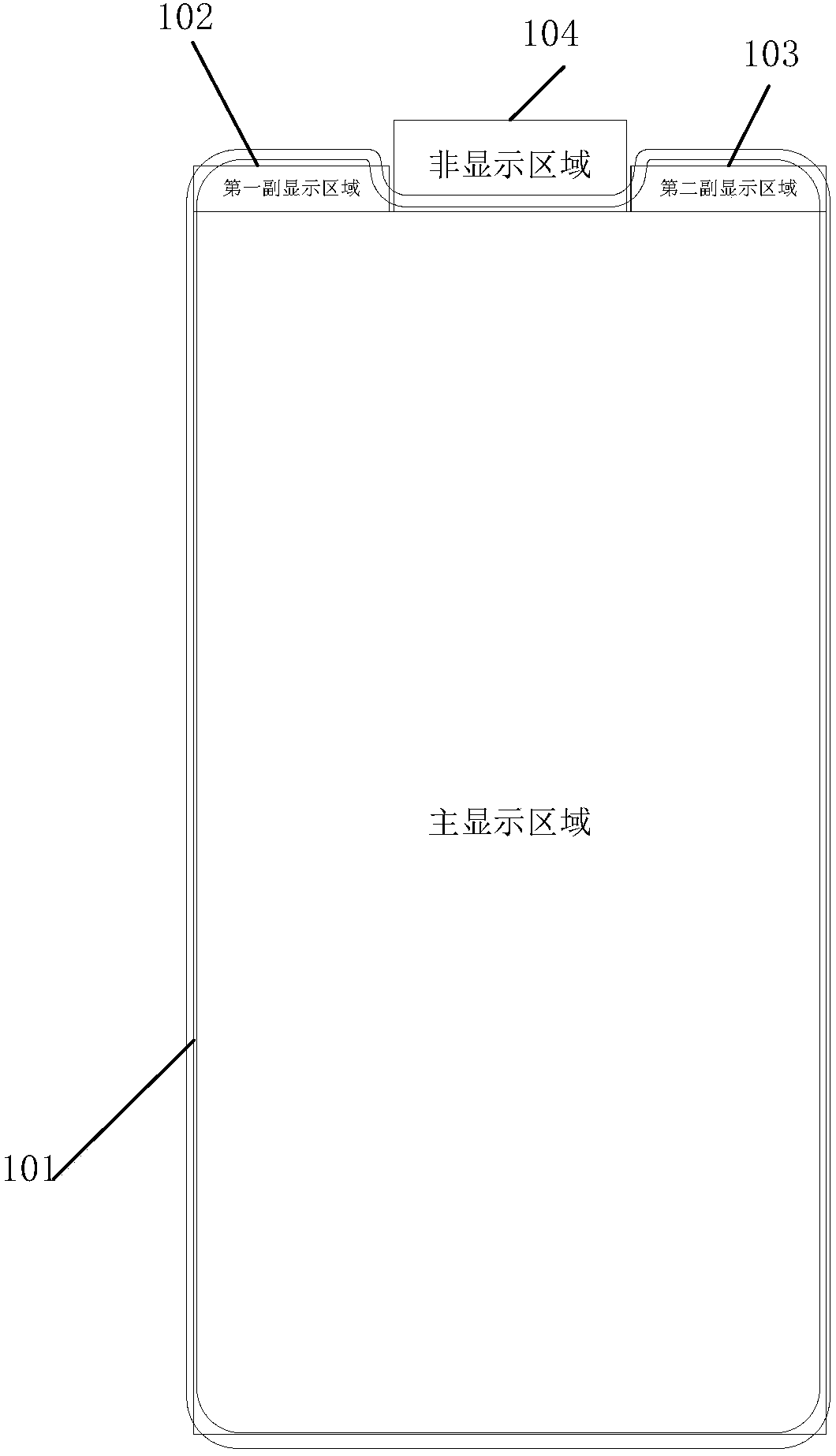
[0056] The driving load compensation unit described in the embodiment of the present invention is applied to a display device, and the display device includes a display panel and a gate driving circuit, and the display panel is divided into a main display area and a sub display area; the sub display area There is at least one row of sub-pixel units inside; the gate drive circuit includes a sub-gate drive sub-circuit, and the sub-gate drive sub-circuit includes ...


PUM


Abstract

The invention provides a driving load compensation unit, method and module and a display device. The driving load compensation unit includes a load compensation control subunit and a resistance-capacitance (RC) load subunit. The RC load subunit includes N switch modules and N RC load modules, where N is an integer greater than 1. A first end of the n-th switch module is connected with a first endof the n-1-th RC load module, and a second end of the n-th switch module is connected with a second end of the n-th RC load module, where n is an integer greater than 1 and less than or equal to N. The load compensation control subunit generates a first load compensation control signal and an n-th load compensation control signal. The n-th switch module is used for controlling the on or off of theconnection between the first end of the n-th switch module and the second end of the n-th switch module under the control of the n-th load compensation control signal. According to the invention, theproblem of difference in luminance resulting from uneven pixel driving currents in main and sub display areas is solved.

Description

technical field [0001] The invention relates to the technical field of display driving, in particular to a driving load compensation unit, method, module and display device. Background technique [0002] Figure 1A It is a schematic diagram of a display panel in a full-screen borderless form. The display panel is as follows: a main display area 101 for conventional display; a first sub-display area 102 for special display; a second sub-display area 103 for special display; And, avoid the non-display area 104 of the mobile phone camera and the earpiece. In order to avoid the camera and earpiece of the mobile phone, there will be a grooved area with a certain depth and width on the top of the display panel, which divides the top display area into two sub-display areas. Since the number of sub-pixel units per row in each sub-display area is less than the number of sub-pixel units per row in the main display area, the load of the main gate drive unit corresponding to the main d...

Claims


Application Information

Patent Timeline
Patent Type & Authority Applications(China)
IPC IPC(8): G09G3/20
CPCG09G3/20G09G2320/0233G09G2310/0267
Inventor 童振霄龙跃
Owner BOE TECH GRP CO LTD
Why Eureka
Try Eureka