
Vibration-isolation mounting device for building electrical equipment

An installation device and building electrical technology, applied in the direction of mechanical equipment, non-rotating vibration suppression, supporting machines, etc., can solve problems such as poor vibration isolation effect, noise pollution, and damage to building structures, so as to eliminate slight vibration, reduce impact, The effect of improving the vibration isolation effect

Inactive Publication Date: 2018-07-13
LIAONING UNIVERSITY OF TECHNOLOGY
View PDF6 Cites 1 Cited by
  • Summary
  • Abstract
  • Description
  • Claims
  • Application Information

AI Technical Summary

Problems solved by technology

[0002] At present, in high-rise buildings, construction facilities such as fans, cooling towers, and water pumps are often installed in the basement or top floor of the building. The above-mentioned facilities will generate vibration during operation. When the vibration is transmitted to the building, it will not only damage the building structure, but also produce Certain noise pollution, in order to solve this problem, when the equipment is installed, the way of installing vibration isolation installation device at the bottom of the equipment is usually adopted. Most of the existing vibration isolation installation devices use a floating plate to buffer the vibration generated by the facility, while Most of the existing floating plates can only move up and down, and can only perform single-layer vibration isolation, and the vibration isolation effect is not good

Method used


Image

  • Vibration-isolation mounting device for building electrical equipment
  • Vibration-isolation mounting device for building electrical equipment

Examples


Embodiment

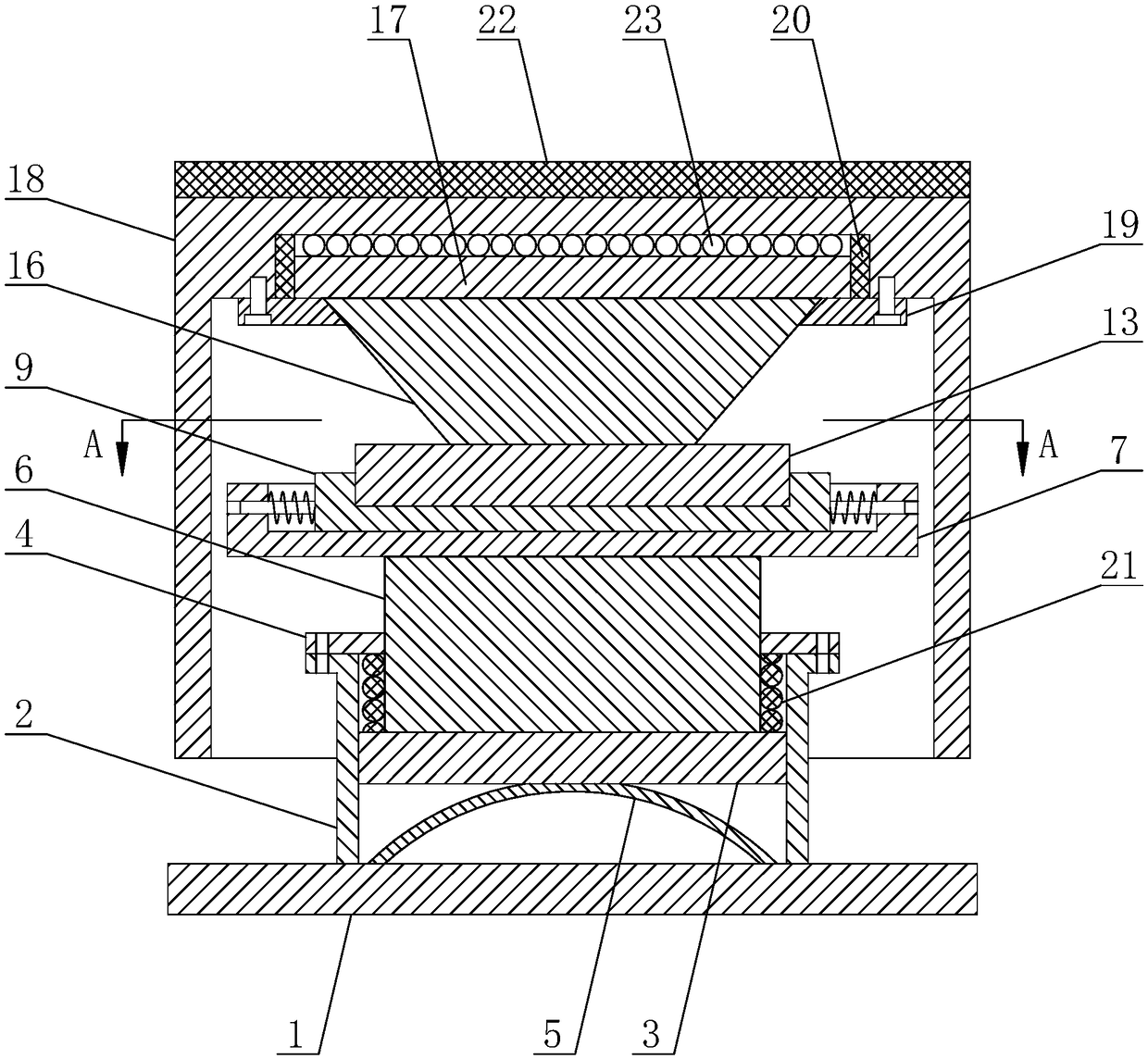
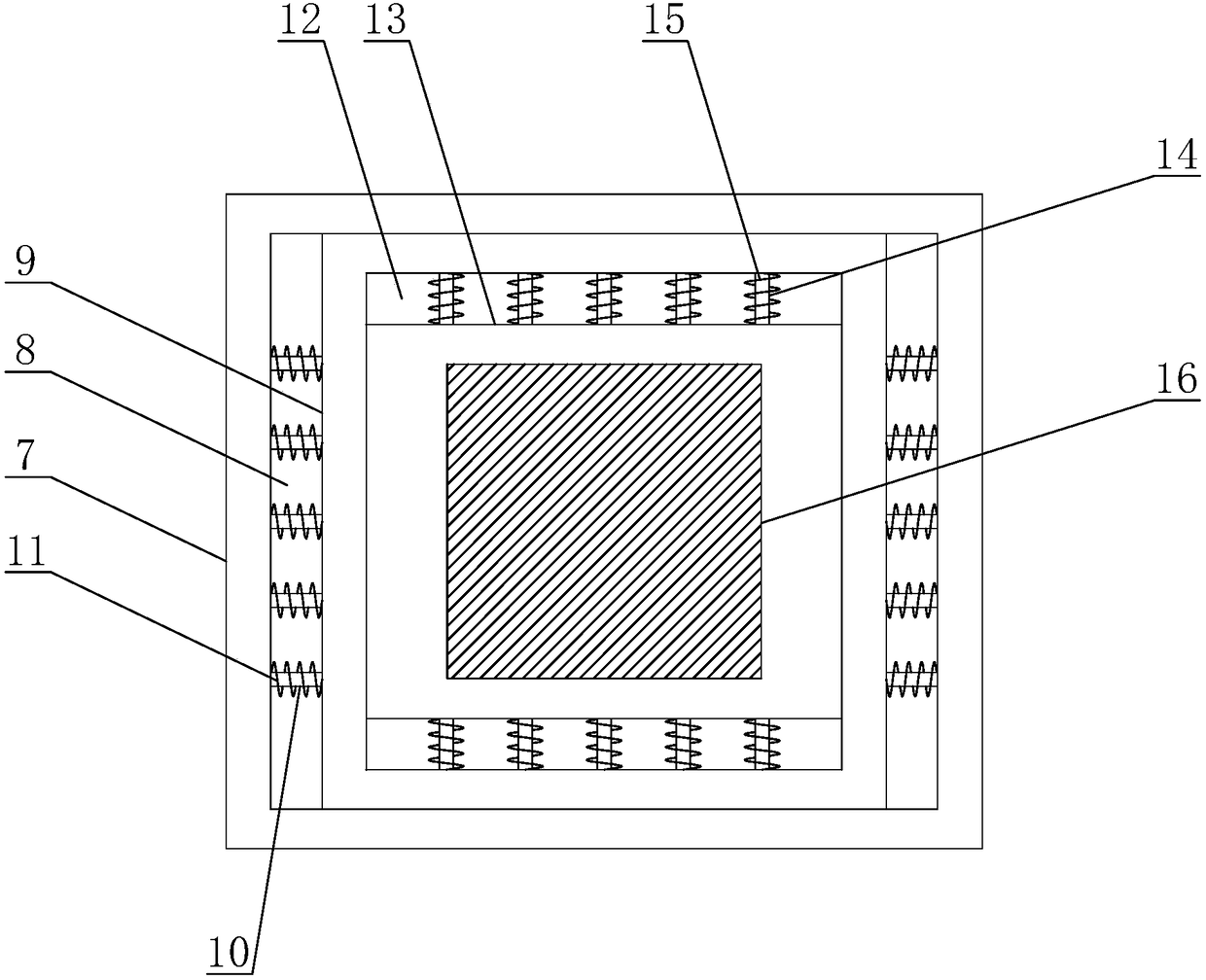
[0022] Embodiment: The present invention is a vibration isolation installation device for building electrical equipment, which includes a base 1, which is provided with mounting holes, and the base 1 is fixedly installed on a building. The top of the base 1 is welded with a support cylinder 2, and the support cylinder 2 is provided with a support block 3, the support block 3 is cylindrical, the outer diameter of the support block 3 is slightly smaller than the inner diameter of the support cylinder 2, the support block 3 can be The support tube 2 slides up and down. The top of the support tube 2 is provided with a locking cap 4 adapted to the support block 3. The locking cap 4 is detachably connected to the support tube 2 by a screw, and the locking cap 4 prevents the support block 3 from coming out of the support tube 2 Slide out. The bottom of the support block 3 is provided with a leaf spring 5, and the leaf spring 5 is used to eliminate up and down vibration. The top of t...


PUM


Abstract

The invention discloses a vibration-isolation mounting device for building electrical equipment, and mainly relates to the field of building equipment mounting. The vibration-isolation mounting devicecomprises a base, wherein a supporting barrel is arranged on the top of the base; a supporting block is arranged in the supporting barrel; a plate spring is arranged on the bottom of the supporting block; a supporting column is arranged on the top of the supporting block; a first supporting plate is arranged on the top of the supporting column; a first groove is formed in the top of the first supporting plate; a second supporting plate is arranged in the first groove; a second groove is formed in the top of the second supporting plate; a third supporting plate is arranged in the second groove; a bracket is arranged on the top of the third supporting plate; a fourth supporting plate is arranged on the top of the bracket; and a floating plate is arranged at the upper side of the fourth supporting plate. The vibration-isolation mounting device has the beneficial effects that: vibrations in the up-down direction, the left-right direction and the front-rear direction can be simultaneouslyeliminated through multi-stage multi-layer buffer, and influences, on a building structure, of facility operation can be effectively reduced.

Description

Technical field [0001] The invention relates to the field of construction equipment installation, in particular to a vibration isolation installation device for building electrical equipment. Background technique [0002] At present, in high-rise buildings, building facilities such as fans, cooling towers, and water pumps are often installed in the basement or top of the building. The above facilities will produce vibration during operation. When the vibration is transmitted to the building, it will not only harm the building structure, but also produce In order to solve the problem of noise pollution, during equipment installation, a vibration isolation installation device is usually installed at the bottom of the equipment. Most existing vibration isolation installation devices use a floating plate to buffer the vibration generated by the facility. Most of the existing floating boards can only move up and down, and can only perform single-layer vibration isolation, and the vibr...

Claims


Application Information

Patent Timeline
Patent Type & Authority Applications(China)
IPC IPC(8): F16M13/02F16F15/04
CPCF16F15/04F16M13/02
Inventor 孙晶高博
Owner LIAONING UNIVERSITY OF TECHNOLOGY
Learn More