LED lamp

A technology of LED lamps and LED circuit boards, which is applied in lighting and heating equipment, instruments, portable lighting devices, etc., can solve the problems of poor screen display effect, reduced screen display effect, uneven lighting, etc., to improve display effect, Improve lighting effects and uniform lighting effects

Pending Publication Date: 2018-07-13
中科同德(北京)生态科技有限公司
View PDF6 Cites 0 Cited by
  • Summary
  • Abstract
  • Description
  • Claims
  • Application Information

AI Technical Summary

Problems solved by technology

[0002] With the advancement of technology in the field of household appliances, the public has higher and higher requirements for household appliances. In order to have a personalized appearance, the existing LED lights are also equipped with screens, and LED light points are set on the periphery of the screen to achieve Lighting function, but the above settings will cause the light from the LED light point to leak to the screen, which will make the screen display effect worse. At the same time, the above settings will also easily cause problems such as penetrating LED lights and uneven lighting. Generally, the solution to this problem The method is to increase the number of LED lights, but the above solutions will further reduce the display effect of the screen

Method used


Image

  • LED lamp
  • LED lamp
  • LED lamp

Examples


Embodiment 1

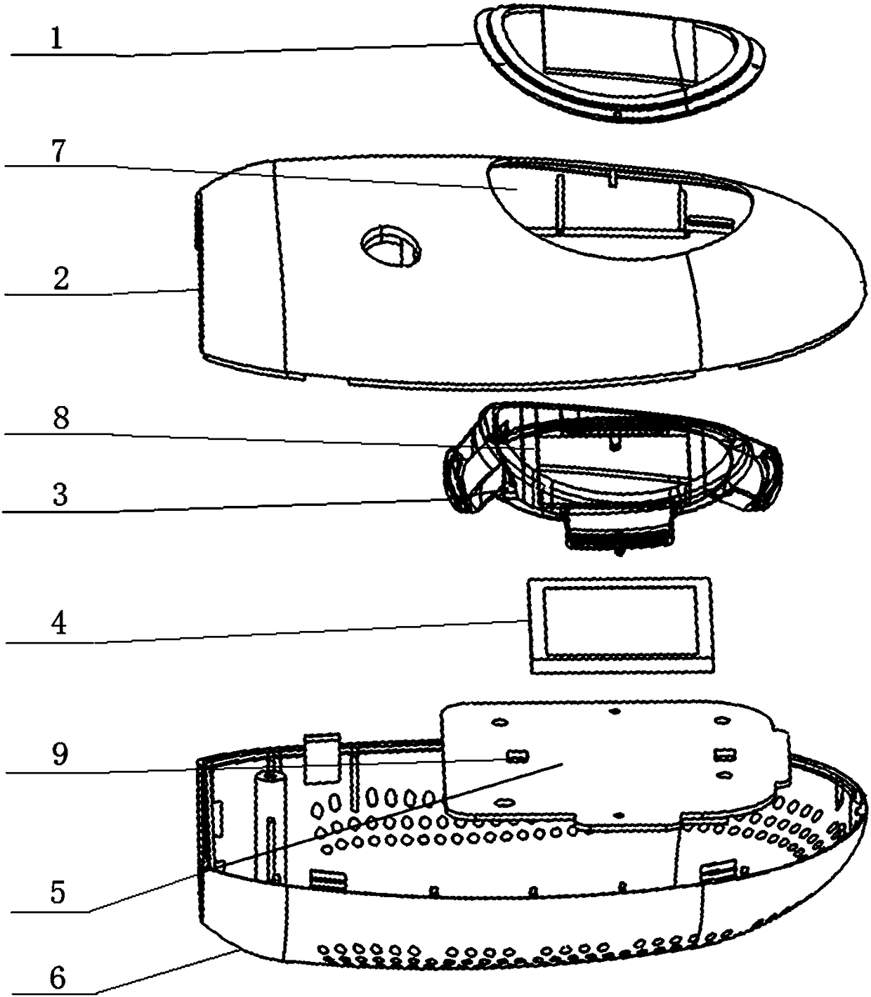
[0037] In this embodiment, the LED circuit board 5 is further provided with a light guide body 3, the light guide body 3 includes a light incident portion 15 vertically fixed on the LED circuit board 5 and covering the periphery of the LED light spot 9 The upper side of the light incident part 15 is provided with a light guide part 14 that is inclined upward relative to the horizontal plane. The light guide part 14 is connected to form a ring-shaped structure through the side part, and is surrounded by the light blocking wall 8, so that the light from the LED lamp point 9 passes through the light guide. The light is emitted from the light-transmitting place on the upper side of the light part 14 .

[0038] In the existing LED lights, problems such as dot penetration and uneven lighting are prone to occur. The general solution to this problem is to increase the number of LED lights, but the above solutions will further reduce the display effect of the screen. At the same time, ...

Embodiment 2

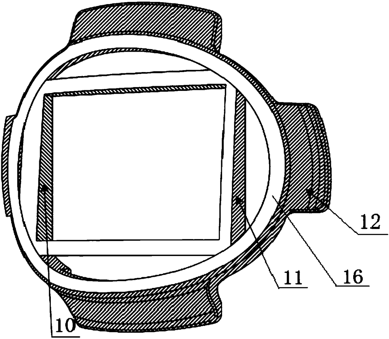
[0043] In this embodiment, the light guide part 14 includes a reflector 12 , so that the light from the LED lamp point 9 exits the light guide part 14 upward relative to the horizontal plane.

[0044] The light guide part 14 with the above structure allows the light from the LED lamp point 9 to irradiate upward relative to the horizontal surface, thereby improving the utilization rate of the light.

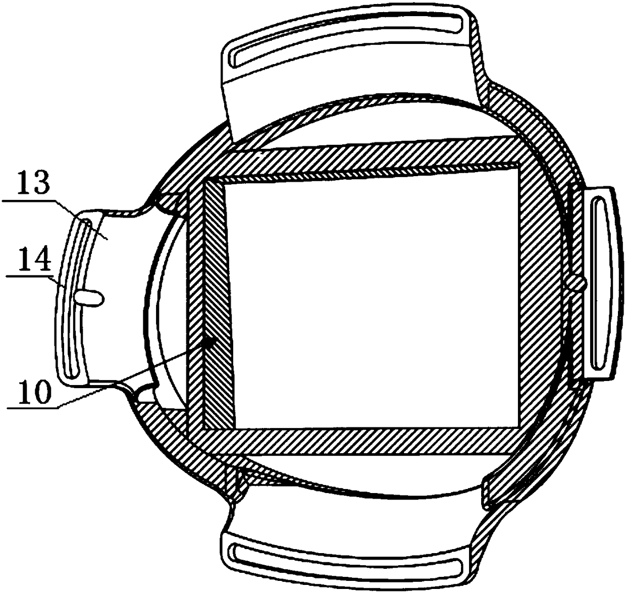
[0045] The light guiding part 14 is inclined toward the light blocking wall 8, and the light guiding part 14 also includes a light-transmitting plate 13 arranged between the light reflecting plate 12 and the light blocking wall 8 for emitting light from the LED lamp point 9, so that the LED lamp The light at point 9 exits the light guide part 14 upward relative to the horizontal plane.

[0046]Through the above arrangement, the light from the LED lamp spot 9 emitted from the light guide part 14 can be irradiated on the outer wall of the light-shielding wall 8, and reflected and di...

Embodiment 3

[0054] In this embodiment, the lower end surface of the light incident part 15 is provided with a screw column extending vertically downward, the screw column passes through the LED circuit board 5 and is fixedly plugged with the screw, so that the LED circuit board 5 is clamped and fixed on the On the screw column between the lower end surface of the light incident part 15 and the screw nut.

[0055] After placing the LED light point 9 inside the light incident part 15, the light incident part 15 and the LED circuit board 5 are fixedly connected by screws to complete the setting of the light guide structure of the LED light. The above settings make the assembly of the LED light more efficient. For simplicity and speed.

[0056] The light guide body 3 is fixedly connected with the light blocking wall 8 to form an integral structure.

[0057] The above configuration makes the installation of the light guide 3 and the light blocking wall 8 simpler and quicker, and only needs to...


PUM


Abstract

The invention relates to an LED lamp. The lamp comprises an LED circuit board, a screen and LED lamp points located on the periphery of the screen are arranged on the LED circuit board, and the LED circuit board is further provided with a light sheltering wall which is located between the screen and the LED lamp points and covers the periphery of the screen so as to prevent the light of the LED lamp points from irradiating the screen. Through the light sheltering wall, the screen and the LED lamp points can be partitioned, meanwhile, a light reflecting part and a light absorbing part are arranged on the outer wall and the inner wall of the light sheltering wall correspondingly, light, irradiated to the screen, of the LED lamp points can be effectively reduced, the screen display effect canbe improved, light of the LED lamp points can be subject to reflecting emission through a light guide body, a point light source is converted into belt light source, point penetration of the LED lampcan be avoided, and lamplight of the LED lamp is more uniform.

Description

technical field [0001] The invention relates to an LED lamp. Background technique [0002] With the advancement of technology in the field of household appliances, the public has higher and higher requirements for household appliances. In order to have a personalized appearance, the existing LED lights are also equipped with screens, and LED light points are set on the periphery of the screen to achieve Lighting function, but the above settings will cause the light from the LED light point to leak to the screen, which will make the screen display effect worse. At the same time, the above settings will also easily cause problems such as penetrating LED lights and uneven lighting. Generally, the solution to this problem The method is to increase the number of LED lamp points, but the above solutions will further reduce the display effect of the screen. [0003] In view of this, the present invention is proposed. Contents of the invention [0004] The purpose of the present...

Claims


Application Information

Patent Timeline
Patent Type & Authority Applications(China)
IPC IPC(8): F21K9/20F21K9/65F21K9/68F21V1/00F21V7/00F21V19/00F21V31/00F21V8/00F21Y115/10
CPCF21V1/00F21V7/00F21V19/003F21V31/005F21V2200/00
Inventor 徐广勇冯启源王禹稼马建伟廉季平孙熙航贾永超
Owner 中科同德(北京)生态科技有限公司
Why Eureka
Try Eureka