Supercharge Your Innovation With Domain-Expert AI Agents!

Logistics status real-time monitoring device

A technology for real-time monitoring and logistics status, applied to alarms, instruments, and anti-theft alarm machines that rely on broken/disturbed straightened ropes/metal wires to start, etc., can solve business disputes, valuables dropped, lost, etc. question

Pending Publication Date: 2018-07-13
BEIJING UNIV OF TECH
View PDF5 Cites 0 Cited by
  • Summary
  • Abstract
  • Description
  • Claims
  • Application Information

AI Technical Summary

Problems solved by technology

For a long time in the past, the transportation packaging technology and control measures in the transportation process of various industries in our country were not perfect. Some valuable commodities had no anti-tampering measures because the packaging box was sealed (that is, it can be resealed without leaving traces after opening) , it is easy for valuables to be dropped or lost during logistics and transportation, which can easily lead to business disputes

Method used


Image

  • Logistics status real-time monitoring device
  • Logistics status real-time monitoring device
  • Logistics status real-time monitoring device

Examples


Embodiment 1

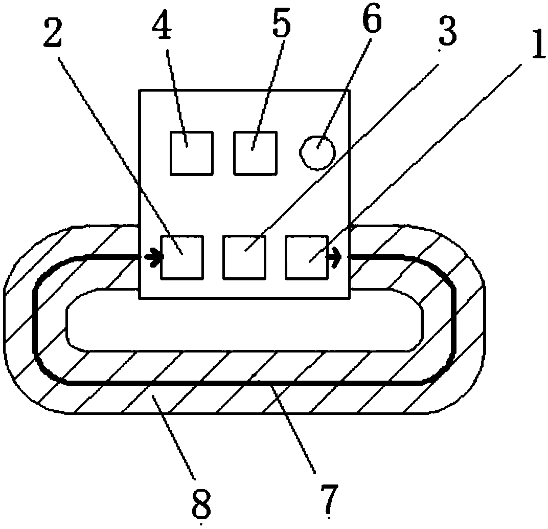
[0027] figure 1 and Figure 4 A preferred embodiment of a real-time monitoring device for logistics status according to the present invention is shown. As shown in the figure, the logistics status real-time monitoring device includes a housing, a control unit 3, a laser emitting unit 1, a laser receiving unit 2, an alarm unit, a laser transmission fiber 7 and an adhesive tape 8 for packaging a packing box, wherein the control unit 3 , The laser emitting unit 1 and the laser receiving unit 2 are located in the housing; the laser emitting unit 1 is connected to the input end of the laser transmission fiber 7, the laser receiving unit 2 is connected to the output end of the laser transmission fiber 7, and the laser transmission fiber 7 is connected to the adhesive tape 8 , when the adhesive tape 8 is pasted on the seal of the packing box, at least part of the laser transmission optical fiber 7 intersects the length direction of the seal; the control unit 3 is connected with the ...

Embodiment 2

[0037] This embodiment is basically the same as Embodiment 1. For the sake of brevity, in the description process of this embodiment, the same technical features as Embodiment 1 will not be described, and only the differences between this embodiment and Embodiment 1 will be described:

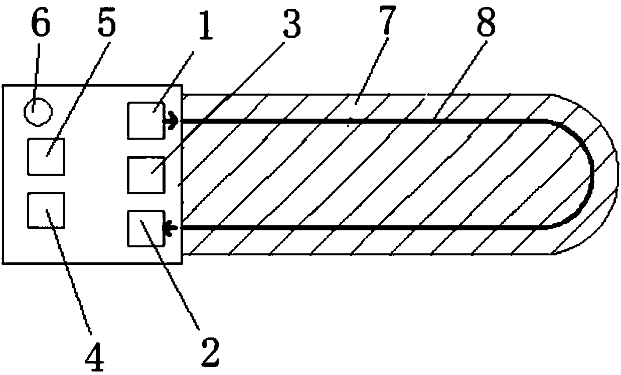
[0038] Such as figure 2 As shown, in this embodiment, the laser receiving unit 2 and the laser emitting unit 1 are located on the same side of the housing, the input end of the laser transmission fiber 7 corresponds to one end of the tape 8, and the output end of the laser transmission fiber 7 is connected to the tape 8 corresponding to the other end. That is to say, both the laser transmission optical fiber 7 and the adhesive tape have a U-shaped structure. When in use, stick the tape 8 of the real-time logistics status monitoring device on the seal of the packaging box, specifically, one side of the U-shaped structure of the laser transmission optical fiber 7 is located on the side of the s...

Embodiment 3

[0040] This embodiment is basically the same as Embodiment 1. For the sake of brevity, in the description process of this embodiment, the same technical features as Embodiment 1 will not be described, and only the differences between this embodiment and Embodiment 1 will be described:

[0041] Such as image 3 As shown, in this embodiment, the laser receiving unit 2 and the laser emitting unit 1 are located on the same side of the housing, the input end and the output end of the laser transmission fiber 7 are located at the same end of the adhesive tape 8, and the laser transmission fiber 7 has a U-shaped structure . So that when the adhesive tape 8 of the logistics status real-time monitoring device is pasted on the seal of the packaging box, one side of the U-shaped structure of the laser transmission fiber 7 is located on one side of the seal, and the other side of the U-shaped structure The part is located on the other side of the seal, and it is easy to break the laser t...


PUM


Abstract

The invention relates to the technical field of logistics, and discloses a logistics status real-time monitoring device. The device comprises a shell, a control unit, a laser emitting unit, a laser receiving unit, a laser transmission optical fiber, an alarm unit and an adhesive tape for packaging a packaging box. The control unit, the laser emitting unit and the laser receiving unit are located in the shell. The laser emitting unit is connected to the input end of the laser transmission optical fiber. The laser receiving unit is connected to the output end of the laser transmission optical fiber. The laser transmission optical fiber is connected with the adhesive tape. When the adhesive tape is stuck to the sealing part of the packaging box, at least one part of the laser transmission optical fiber intersects the length direction of the sealing part. The control unit is respectively connected with the laser emitting unit, the laser receiving unit and the alarm unit. The control unit is internally provided with an electronic identity identifier. As a result, the real-time location of a product and the packaging status of the product during the logistics and transportation process can be monitored. Meanwhile, the device has a positive impact on the safety and the quality management of current logistics and transportation products.

Description

technical field [0001] The invention relates to the technical field of logistics, in particular to a real-time monitoring device for logistics status. Background technique [0002] With the rapid development of the logistics and express delivery industry, many valuables are transported in the form of express delivery or logistics. Neither the recipient nor the sender wants the items to be opened or stolen during transportation. Therefore, real-time monitoring technology for logistics transportation is a modern logistics industry. One of the important directions of development. For a long time in the past, the transportation packaging technology and control measures in the transportation process of various industries in our country were not perfect. Some valuable commodities had no anti-tampering measures because the packaging box was sealed (that is, it can be resealed without leaving traces after opening) , It is easy for valuables to be dropped or lost during logistics an...

Claims


Application Information

Patent Timeline
Patent Type & Authority Applications(China)
IPC IPC(8): G08B13/12
CPCG08B13/126
Inventor 王智勇秦文斌刘友强向美华
Owner BEIJING UNIV OF TECH
Features
  • R&D
  • Intellectual Property
  • Life Sciences
  • Materials
  • Tech Scout
  • Unparalleled Data Quality
  • Higher Quality Content
  • 60% Fewer Hallucinations
Learn More