Speed and key phase integrated detection system for rotating machines

A detection system, a technology for rotating machinery, applied in the testing of mechanical components, the testing of machine/structural components, and the testing of machine gears/transmission mechanisms. To achieve the effect of easy control, wide applicability and compact structure

Inactive Publication Date: 2018-07-17
HUAZHONG UNIV OF SCI & TECH
View PDF6 Cites 3 Cited by
  • Summary
  • Abstract
  • Description
  • Claims
  • Application Information

AI Technical Summary

Benefits of technology

This technology helps improve detecting systems quickly while also providing accurate data on their movement or position within them. It uses multiple probes instead of just two at once during each measurement period, making this technique more efficient than previous techniques.

Problems solved by technology

This patents discuss various techniques related to measuring rotation speed and phases during failure detection processes. These include traditional approaches like physical contact measurements (mechanic) and optics/inductance systems. While these technologies offer high accuracy but they require large spaces within machines due to limitations associated with mounting and positioning sensory equipment. Additionally, while some recent proposals involve combining electrical and inductive elements together through triboelectrodes, none currently exist today.

Method used


Image

  • Speed and key phase integrated detection system for rotating machines
  • Speed and key phase integrated detection system for rotating machines
  • Speed and key phase integrated detection system for rotating machines

Examples


Embodiment approach

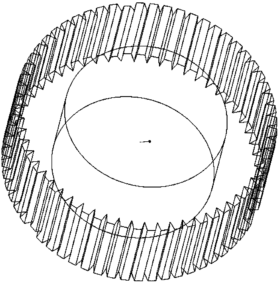
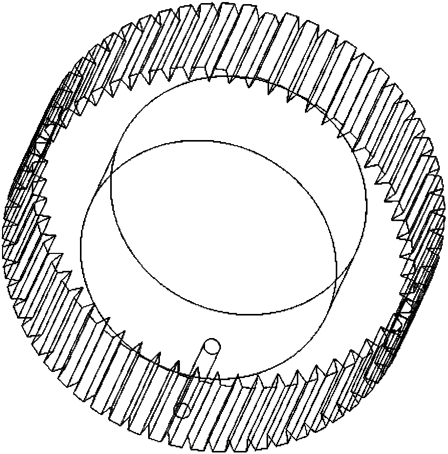
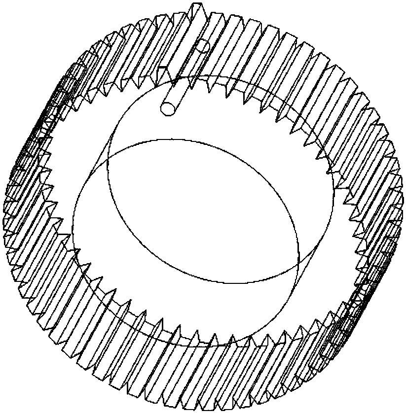
[0038] In addition, besides the way of tooth height change, the compensation tooth can also be realized in another form, and the required technical effect can also be obtained. According to another preferred embodiment of the present invention, another type of integrated detection system is also provided, which also includes a gear component, a tooth height measurement probe and a signal processing unit, and its difference mainly focuses on the design of the gear component, and other The components are largely the same. According to a preferred embodiment of the present invention, the imbalance compensation structure can be in the form of a balance hole, and the balance hole and phase teeth are designed to be distributed on both sides of the gear plate.

[0039] Such as Figure 2a Or as shown in 2b, the gear part is used to be concentrically fixed with the rotating element as the test object, and the rotation test is performed together; the gear part has a plurality of teeth,...


PUM


Abstract

The invention belongs to the field of supporting detection equipment for rotating machines, and discloses a speed and key phase integrated detection system for rotating machines. The system includes agear component, a tooth height measuring probe and a signal processing unit. The gear component includes a phase tooth with tooth height different from that of the other normal teeth, and is providedwith a compensation tooth or a balance hole in order to make compensation for the unbalance caused by the phase tooth. The tooth height measuring probe is used for acquiring change signals of the gapbetween the tooth height measuring probe and the outer end faces of the teeth of the gear component in real time. The signal processing unit is used for receiving the signals from the tooth height measuring probe, calculating the real-time speed based on the time and radian information of any two adjacent pulse signals, and identifying and locating the circumferential position of the phase tooth.Compared with the existing scheme, the compactness of the speed and phase detection system can be remarkably improved.

Description


Claims


Application Information

Patent Timeline
Owner HUAZHONG UNIV OF SCI & TECH
Why Eureka
Try Eureka