Cleaning device of micro-motor shell

A technology for cleaning devices and micro-motor casings, which is applied in the direction of cleaning methods using liquids, cleaning methods and utensils, chemical instruments and methods, etc., which can solve the problems of difficult cleaning of micro-motor casings, damage to the life of parts of equipment, and influence on precision. Problems such as degree of difficulty, to achieve the effect of simple structure, high cleaning efficiency, and improved drainage capacity

Pending Publication Date: 2018-07-20
南京康翱峰自动化科技有限公司
View PDF11 Cites 4 Cited by
  • Summary
  • Abstract
  • Description
  • Claims
  • Application Information

AI Technical Summary

Problems solved by technology

After the production of the micro-motor casing is completed, it needs to be cleaned, because metal oxides, oil stains and inorganic salt dirt will form on the surface of the micro-motor casing during the production process, and it may also contain polymers, so if it is not cleaned in time It will affect the use of equipment and damage the life of parts. For the field of precision machinery, it will even affect its accuracy.
[0003] The existing micro-motor shells are mainly cleaned by ultrasonic cleaning devices, and then the micro-motor shells are cleaned manually. The manual cleaning method is not only inefficient, but also the inside of the micro-motor shells is not easy to clean.
[0004] At present, there is a lack of a cleaning device for micro-motor casings with reasonable design and high cleaning efficiency

Method used


Image

  • Cleaning device of micro-motor shell
  • Cleaning device of micro-motor shell
  • Cleaning device of micro-motor shell

Examples


Embodiment Construction

[0017] The following will clearly and completely describe the technical solutions in the embodiments of the present invention with reference to the accompanying drawings in the embodiments of the present invention. Obviously, the described embodiments are only some, not all, embodiments of the present invention.

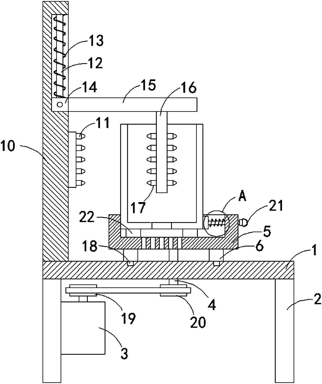
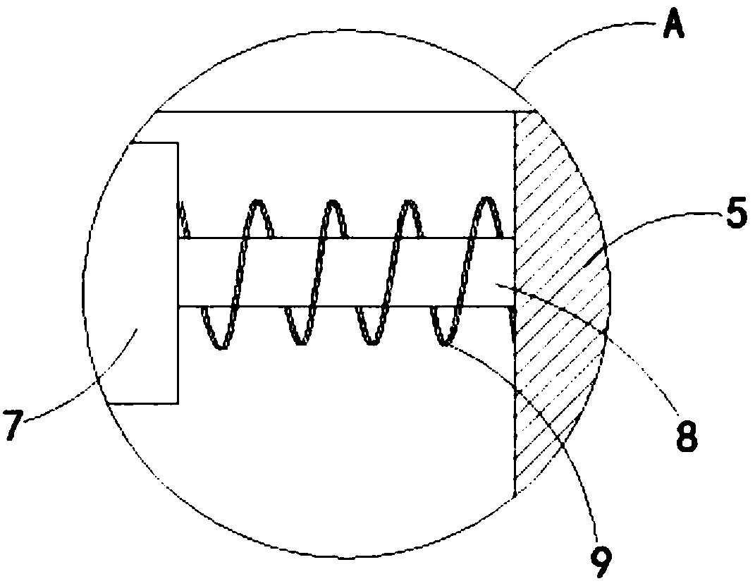
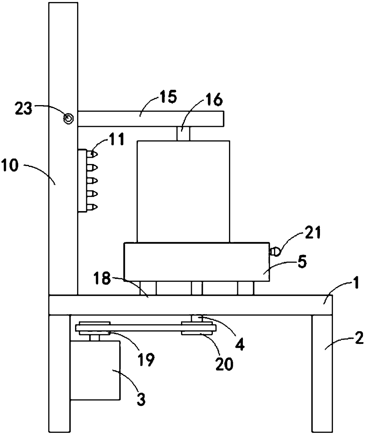
[0018] like Figure 1-3 As shown, a cleaning device for a micro-motor case of the present invention includes a base 1, and both sides of the lower end of the base 1 are fixedly connected with support plates 2, and a drive motor 3 is installed on the side wall of one of the support plates 2, and the base 1 is provided with a rotating shaft 4, and the rotating shaft 4 is connected to the driving motor 3 through a transmission mechanism. Specifically, the transmission mechanism includes a first chain plate 19 coaxially fixedly connected with the driving shaft of the driving motor 3. The rotating shaft 4 is located on the lower side of the base 1 One end coaxially fixedl...


PUM


Abstract

The invention discloses a cleaning device of a micro-motor shell. The device comprises a base, wherein supporting plates are fixedly connected to the two sides of the lower end of the base, a drivingmotor is installed on the side wall of one of the supporting plates, and a rotating shaft penetrates through the base; the rotating shaft is in transmission connection with the driving motor through atransmission mechanism, and a rotating block is fixedly connected above the rotating shaft; supporting blocks are fixedly connected to the lower end of the rotating block, the supporting blocks are in sliding connection with the base, and a containing groove is formed in the upper end of the rotating block; a clamping plate is arranged in the containing groove, a first sliding rod is fixedly connected to the side wall of the clamping plate, and the end, far away from the clamping plate, of the first sliding rod penetrate through the side wall of the rotating block; and a first spring sleevesthe part, located in the containing groove, of the first sliding rod, the two ends of the first spring are correspondingly and fixedly connected with the clamping plate and the side wall of the containing groove, and a vertical plate is fixedly connected to the upper end of the base. The cleaning device of the micro-motor shell is simple in structure, convenient to use, time-saving and labor-saving, and high in cleaning efficiency.

Description

technical field [0001] The invention relates to the technical field of mechanical cleaning, in particular to a cleaning device for a micro-motor casing. Background technique [0002] With the further demand for home appliances in modern life, high-volume, high-quality, low-cost products meet people's consumption needs. Micro motor is the core component of all kinds of household motors, and its quality directly affects the service life of household appliances. The casing is the core part of the micro-motor, and its precision and consistency determine the quality of the micro-motor. After the production of the micro-motor casing is completed, it needs to be cleaned, because metal oxides, oil stains and inorganic salt dirt will form on the surface of the micro-motor casing during the production process, and it may also contain polymers, so if it is not cleaned in time It will affect the use of equipment and damage the life of parts. For the field of precision machinery, it wi...

Claims


Application Information

Patent Timeline
Patent Type & Authority Applications(China)
IPC IPC(8): B08B3/02B08B3/10B08B13/00
CPCB08B3/022B08B3/10B08B13/00
Inventor 张良柱倪斐
Owner 南京康翱峰自动化科技有限公司
Why Eureka
Try Eureka