Workpiece sliding locking device of automatic turning lathe

A technology of sliding locking and automatic lathes, which is applied in the direction of positioning devices, auxiliary devices, tool holder accessories, etc., can solve the problems of inconsistent height, poor versatility, and inability to achieve two-way fixing at the same time

Inactive Publication Date: 2018-07-20
东莞产权投资有限公司
View PDF7 Cites 0 Cited by
  • Summary
  • Abstract
  • Description
  • Claims
  • Application Information

AI Technical Summary

Problems solved by technology

[0003] The existing lathe locking device has the following defects: 1. The automatic lathe itself is bulky and difficult to move. In the prior art, it is usually manually locked by manpower, which is labor-intensive, and the auxiliary time for parts processing is long, which greatly Reduced production efficiency; 2. The design structure is simple, without considering the needs of the vertical telescopic function of the machine tool, the locking requirements in different longitudinal directions, the locking heights of different types of lathes are inconsistent, and the versatility is poor; 3. In the existing locking In order to ensure the real locking stability of the device, often only the end of the device can be fixed, and the two-way fixation cannot be realized at the same time, so it is difficult to achieve locking at any position. fixed selection

Method used


Image

  • Workpiece sliding locking device of automatic turning lathe
  • Workpiece sliding locking device of automatic turning lathe
  • Workpiece sliding locking device of automatic turning lathe

Examples


Embodiment

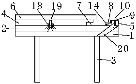
[0019] see figure 1 , the present invention provides a workpiece sliding locking device for an automatic lathe, comprising a slide rail base 1, two guide rails 2 are fixedly installed on the top of the slide rail base 1, and the two guide rails 2 are about the central axis of the slide rail base 1 Symmetrically distributed, the slide rail base 1 provides bottom support for the guide rail 2, which facilitates the installation of the guide rail 2. The two guide rails 2 are symmetrically arranged. When the object moves linearly along the guide rail 2, the guide rail 2 plays the role of supporting and guiding. Lightweight and labor-saving, the guide rail 2 has strong wear resistance, and can still maintain a certain accuracy after long-term use.

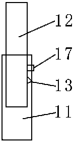
[0020] see figure 1 and figure 2 , the bottom of the slide rail base 1 is connected with several telescopic rods 3, the telescopic rods 3 are composed of a first steel pipe 11 and a second steel pipe 12, the second steel pipe 12 is lo...


PUM


Abstract

The invention discloses a workpiece sliding locking device of an automatic turning lathe. The workpiece sliding locking device comprises a sliding rail base, two guiding rails are mounted at the top of the sliding rail base, and a plurality of telescopic rods are connected to the bottom of the sliding rail bottom. A sliding block is arranged between the two guiding rails, stop blocks are mounted on the upper surfaces of the guiding rails through frames, and the sliding rail base is sleeved with the frames. Clamping positions are arranged on the inner sides of the stop blocks, a worktable is mounted at the top of the sliding block, and a notch is formed in the end, close to the stop blocks, of the sliding block. Inlaid blocks are arranged between the sliding block and the guiding rails andmounted on the sliding blocks through hoops, and the hoops are arranged on the two sides of the sliding block. The sliding effect of a workpiece is achieved, further, by two-way sliding of the slidingblock and the stop blocks, fixing on any position of the guiding rails can be achieved, the requirement of the turning lathe for locking of the workpiece under different conditions can be met, the workpiece sliding locking device can adapt to different heights, through the stop blocks and the notch, the automatic locking effect is achieved on sliding of the sliding block.

Description

technical field [0001] The invention relates to the technical field of sliding locking, in particular to a workpiece sliding locking device for an automatic lathe. Background technique [0002] The automatic lathe is a high-performance, high-precision, low-noise tool-feeding automatic lathe. It is an automatic processing machine tool that controls the processing program through a cam. Its basic core is that it can automatically process the same type for a long time after certain settings and adjustments. product. In the machinery manufacturing industry, automatic machine tools are widely used to process various parts. In the actual processing of lathes, how to effectively lock and fix the workpiece is the main factor that determines the actual processing quality. [0003] The existing lathe locking device has the following defects: 1. The automatic lathe itself is bulky and difficult to move. In the prior art, it is usually manually locked by manpower, which is labor-inten...

Claims


Application Information

Patent Timeline
Patent Type & Authority Applications(China)
IPC IPC(8): B23Q3/00B23B25/00
CPCB23Q3/00B23B25/00
Inventor 关计忠
Owner 东莞产权投资有限公司
Why Eureka
Try Eureka