Multifunctional cleaning roller shutter system

A multi-functional, roller blind technology, applied in cleaning equipment, window cleaning, shading screens, etc., can solve the problems that the curtains are easy to absorb dust and other dirt, affect the service life, and are not easy to clean, etc., to achieve simple, reliable and convenient structure Various production and cleaning steps and excellent effects

Inactive Publication Date: 2018-07-20
苏州市欧贝遮阳科技有限公司
View PDF6 Cites 5 Cited by
  • Summary
  • Abstract
  • Description
  • Claims
  • Application Information

AI Technical Summary

Problems solved by technology

[0002] In real life, light pollution can be seen everywhere, and people pay more and more attention to the sunshade effect of houses. In addition to indoor curtains, people install more sunshade roller blinds outside the windows. The sunshade effect is obvious, but because it is installed outdoors, as shown in Figure 1 Shown as the roller blind structure in the prior art, the rotation of the main shaft 2 drives the roller blind 3 to descend and unfold from the roller blind outlet 4, and the sunshade curtain is exposed for a long time, which makes the curtain easily absorb dust and other dirt, and this kind of sunshade roller blind It is generally installed outside the windows of high-rise buildings, so it is not easy to clean. If it is not cleaned for a long time, it will be involved in the shutter box, and dirt such as dust will accumulate in the shutter box, which is not only unhygienic, but also affects the service life.

Method used


Image

  • Multifunctional cleaning roller shutter system
  • Multifunctional cleaning roller shutter system
  • Multifunctional cleaning roller shutter system

Examples


Embodiment Construction

[0016] The technical solutions of the present invention will be further described below in conjunction with the accompanying drawings and embodiments.

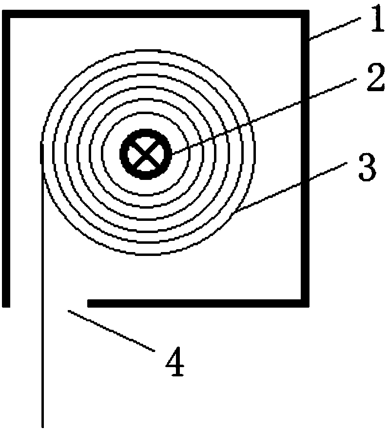
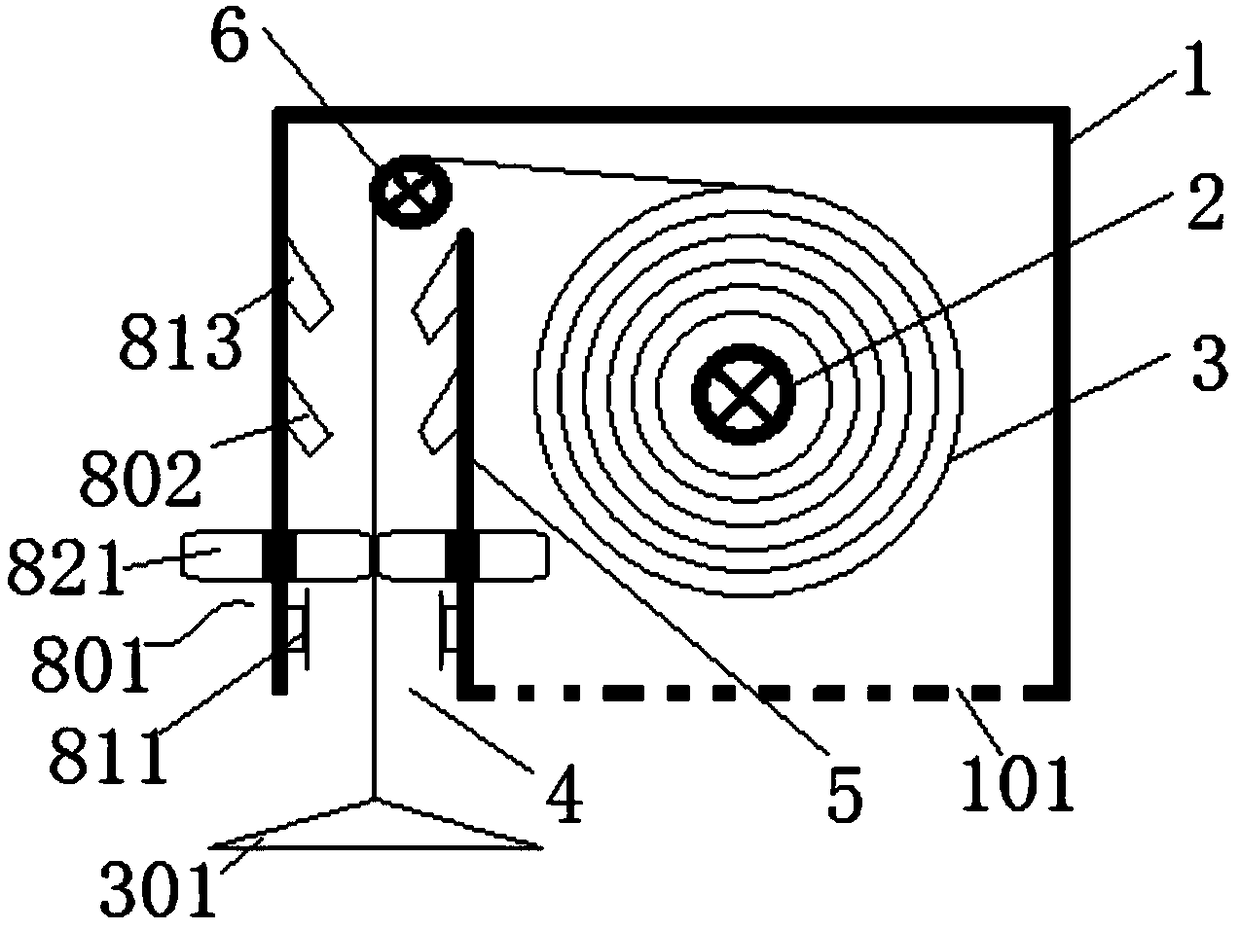
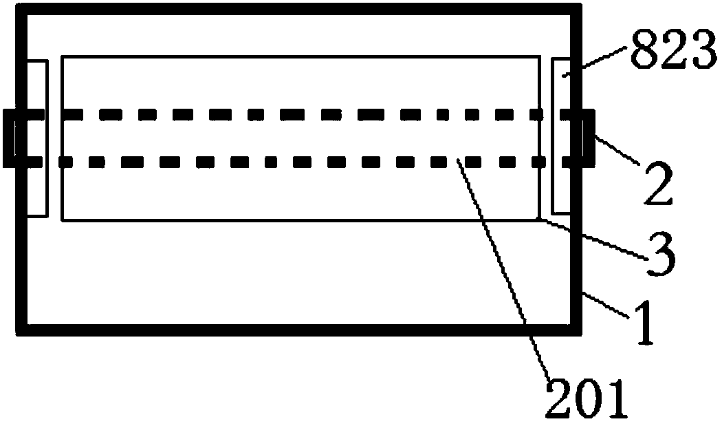
[0017] Such as figure 2 and image 3 The multifunctional cleaning roller shutter system shown includes a roller shutter box 1, a main shaft 2 and a roller shutter 3, the main shaft 2 runs through the entire box along the extension direction of the roller shutter box 1, and one end of the roller shutter 3 is connected to the main shaft 2 and can be Wrapped on the main shaft 2 by the rotation of the main shaft, a shutter outlet 4 is provided under one side of the shutter 3, and an outlet baffle 5 is provided on both sides of the shutter outlet 4 to the inside of the shutter box 1, and the outlet baffles on both sides 5. An outlet baffle channel 7 is formed along the vertical direction on one side inside the rolling shutter box, and a guide shaft 6 is arranged at the end of the baffle channel 7. The guide shaft runs through the...


PUM


Abstract

The invention discloses a multifunctional cleaning roller shutter system. The multifunctional cleaning roller shutter system comprises a roller shutter box, a main shaft and a roller shutter, whereinthe main shaft penetrates through the whole roller shutter box in the extending direction of the roller shutter box. The main shaft is connected to one end of the roller shutter, and the end of the roller shutter can be wound and covered on the main shaft through the rotation of the main shaft. A roller shutter outlet is formed below one side of the roller shutter, and outlet baffles towards the interior of the roller shutter box are arranged at two sides of the roller shutter outlet. The outlet baffles on both sides of the roller shutter outlet form an outlet baffle channel, a guide shaft isarranged at the tail end of the baffle channel, and the guide shaft penetrates through the whole box in the extending direction of the roller shutter box. The roller shutter extends to the outside ofthe roller shutter box through the baffle channel by the guide shaft. The baffle channel is internally provided with a cleaning device, and the cleaning device comprises a decontamination device, a flushing device and a dehumidification device. The multifunctional cleaning roller shutter system has the advantages that the surface of the roller shutter can be cleaned while the roller shutter is retracted, cleaning steps are various and comprehensive, and the cleaning of the interior of the roller shutter box is ensured, the structure is simple and reliable, and manufacture is convenient .

Description

technical field [0001] The invention relates to the field of roller blind cleaning, in particular to a multifunctional cleaning roller blind system. Background technique [0002] In real life, light pollution can be seen everywhere, and people pay more and more attention to the sunshade effect of houses. In addition to indoor curtains, people install more sunshade roller blinds outside the windows. The sunshade effect is obvious, but because it is installed outdoors, as shown in Figure 1 Shown as the roller blind structure in the prior art, the rotation of the main shaft 2 drives the roller blind 3 to descend and unfold from the roller blind outlet 4, and the sunshade curtain is exposed for a long time, which makes the curtain easily absorb dust and other dirt, and this kind of sunshade roller blind It is generally installed outside the windows of high-rise buildings, so it is not easy to clean. If it is not cleaned for a long time, it will be involved in the shutter box, an...

Claims


Application Information

Patent Timeline
Patent Type & Authority Applications(China)
IPC IPC(8): E06B9/42A47L4/00
CPCE06B9/42A47L4/00
Inventor 阙群明陈亚明
Owner 苏州市欧贝遮阳科技有限公司
Why Eureka
Try Eureka