Powder sending and laying device for quickly shaping device

A technology of forming equipment and powder spreading device, which is applied in the field of components of rapid prototyping equipment, can solve problems such as adverse effects on forming quality, affecting the quality of formed parts, and affecting work reliability, etc., to achieve improved powder utilization, simple control, and reliability high effect

Active Publication Date: 2009-02-11
西安赛隆增材技术股份有限公司
View PDF0 Cites 36 Cited by
  • Summary
  • Abstract
  • Description
  • Claims
  • Application Information

AI Technical Summary

Problems solved by technology

[0004] In the rapid prototyping process using powder as raw material, there are generally phenomena such as powder splashing and ball gathering, and some places on the forming surface will have bumps due to the spheroidization effect of the powder. The powder spreading mechanism of the above powder feeding device, moving hopper, scraping Plates, rollers, etc. are all rigid structures, and they are easy to get stuck due to these protrusions during the forward or return journey of powder spreading, so that the process of powder spreading and forming process are interrupted
In order to continue the forming process, the forming platform can be lowered to allow the rollers or scrapers to pass through obstacles, but when the forming platform is lowered, the thickness of the layers will increase, so the forming accuracy in the vertical direction will inevitably decrease, and the excessively thick single-layer powder will also affect the Detrimental effect on the forming quality of the next layer, or even the quality of the entire formed part
[0005] In addition, the rapid prototyping environment of some powders such as metal powders is relatively harsh and special. It requires a heat source with high energy density to clad and form metal powders. will affect the reliability of its operation
If the structure of the powder feeding and spreading device is too complicated, there are too many motion control parts, and the harsh forming environment will inevitably affect the reliability of its normal operation

Method used


Image

  • Powder sending and laying device for quickly shaping device
  • Powder sending and laying device for quickly shaping device
  • Powder sending and laying device for quickly shaping device

Examples


Embodiment Construction

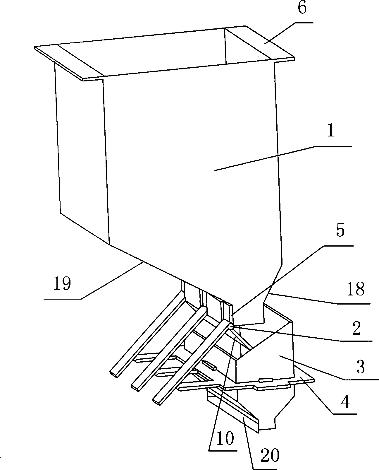
[0030] Such as figure 1 As shown, the present invention includes a powder storage box 1 and a mobile hopper 3, wherein the powder storage box 1 is an upper-mounted powder storage box located above the mobile hopper 3 and having a powder lowering port at the bottom. Moreover, the position of the powder storage box 1 is fixed, and the powder storage box 1 is provided with two left and right installation platform structures 6 which are fixed on the upper part of the forming space of the rapid prototyping equipment. The powder storage box 1 is a rectangular box with an upper opening, and the bottom of the rectangular box is composed of two inclined box bottoms on the left and right and two vertical box bottoms on the front and back. The two inclined box bottoms are both downward and inwardly inclined. The inclination angles are different, and the powder lowering port is a rectangular powder lowering port correspondingly arranged at the bottom of the box bottom. In this embodiment...


PUM

PropertyMeasurementUnit
thicknessaaaaaaaaaa

Abstract

The invention discloses a powder feeding and laying device applied to a high rate former, which consists of a powder storing case and a movable hopper, wherein, the powder storing case is an upper powder storing case positioned above the movable hopper and provided with a power outlet at the bottom; the powder storing case is fixed and stable; a movable baffle capable of automatically opening and closing the powder outlet is arranged at the bottom of the powder outlet; a movable bracket is fixed outside the movable hopper which moves to and fro from left to right along a horizontal line on a forming working platform of a high rate former by a driving mechanism; an unlocking component which is matched to be used with the movable bracket is arranged on the movable baffle; a receiving port at the upper part of the movable hopper corresponds to the powder outlet; a powder laying port is arranged at the bottom of the movable hopper, which is a rectangular port enclosed by two lateral baffles in the front and the back and two flexible doctor blades on the left and the right. The powder feeding and laying device applied to a high rate former has simple structure, handy assembly and deinstallation of all parts and easy regulation and control, the capability of modular working independently, rapid powder laying, and high reliability.

Description

technical field [0001] The invention relates to a component of rapid prototyping equipment using powder as a raw material and adopting a selective deposition / sintering / melting process, in particular to a powder feeding device for rapid prototyping equipment. Background technique [0002] At present, the rapid prototyping technology of parts using powder as raw material and through the selective deposition / sintering / melting process is a hotspot in the field of rapid manufacturing. Typical technologies include: Selective Laser Sintering (SLS), selective laser sintering Melting (SelectiveLaser Melting, SLM), electron beam melting (Electron Beam melting, EBM), three-dimensional printing (Three Dimensional Printing, 3DP). The technological process of the above-mentioned technologies is similar: first, a layer of raw material powder is laid on the processing plane, and then the processing source divides the powder according to the cross-sectional shape of the part, and finally for...

Claims


Application Information

Patent Timeline
Patent Type & Authority Applications(China)
IPC IPC(8): B22F3/00B65G65/40B22F12/52B22F12/67
Inventor 贺卫卫汤慧萍贾文鹏刘海彦
Owner 西安赛隆增材技术股份有限公司
Why Eureka
Try Eureka