Rectifying device of vehicle AC generator

A technology for alternators and rectifiers, applied in electromechanical devices, cooling/ventilation devices, electrical components, etc., can solve the problems of cooling function decline, solder flow, poor cooling performance, etc., to prevent damage and prevent solder flow , The effect of reducing the manpower required for assembly

Inactive Publication Date: 2005-03-23
VALEO ELECTRICAL SYST KOREA
View PDF0 Cites 6 Cited by
  • Summary
  • Abstract
  • Description
  • Claims
  • Application Information

AI Technical Summary

Problems solved by technology

[0006] That is, the amount of air flow forcefully transferred by the cooling fan 43 is evenly distributed radially with respect to the rotating shaft 10 of the cooling fan 43, and the closer to the central part, the better the cooling effect. However, when the diodes are arranged in a straight line as before, the The cooling function of the diodes far from the central part will be reduced
[0007] Second, auxiliary diodes 63 are used for the rectification function, and these auxiliary diodes 63 are usually arranged between the heat sink 64 and the terminal board 61, so the cooling function is greatly reduced
[0008] That is, the main diode 62 plays the role of converting the three-phase alternating current from the stator into a direct current, and the auxiliary diode 63 plays a self-generating function of supplying an exciting current to the field current, but they are assembled in such a way that they are buried in the The structure between the heat sink 64 and the terminal pad 61, so its cooling performance is not good
[0009] The 3rd, the terminal portion 62a of these diodes 62 must be welded after passing through the terminal hole 61a of the terminal plate 61, but the diameters of the beginning part and the end portion of the thickness of the terminal plate 61 of the terminal hole 61a are equal, so its installation becomes easier. difficult
[0010] More specifically, the terminal portion 62a of the diode 62 is inserted into the terminal hole 61a of the terminal board 61 and then connected to the coil of the stator 50 for soldering. Small, in such a small state of the terminal hole 61a, because the hole is the same up and down, it is difficult to assemble the terminal part 62a.
[0011] Other than that, not only are there no parts to keep excess solder from bleeding when soldering, but there are also no parts to guide the stator coils

Method used


Image

  • Rectifying device of vehicle AC generator
  • Rectifying device of vehicle AC generator
  • Rectifying device of vehicle AC generator

Examples


Embodiment Construction

[0021] The present invention will be described in detail below with reference to the accompanying drawings.

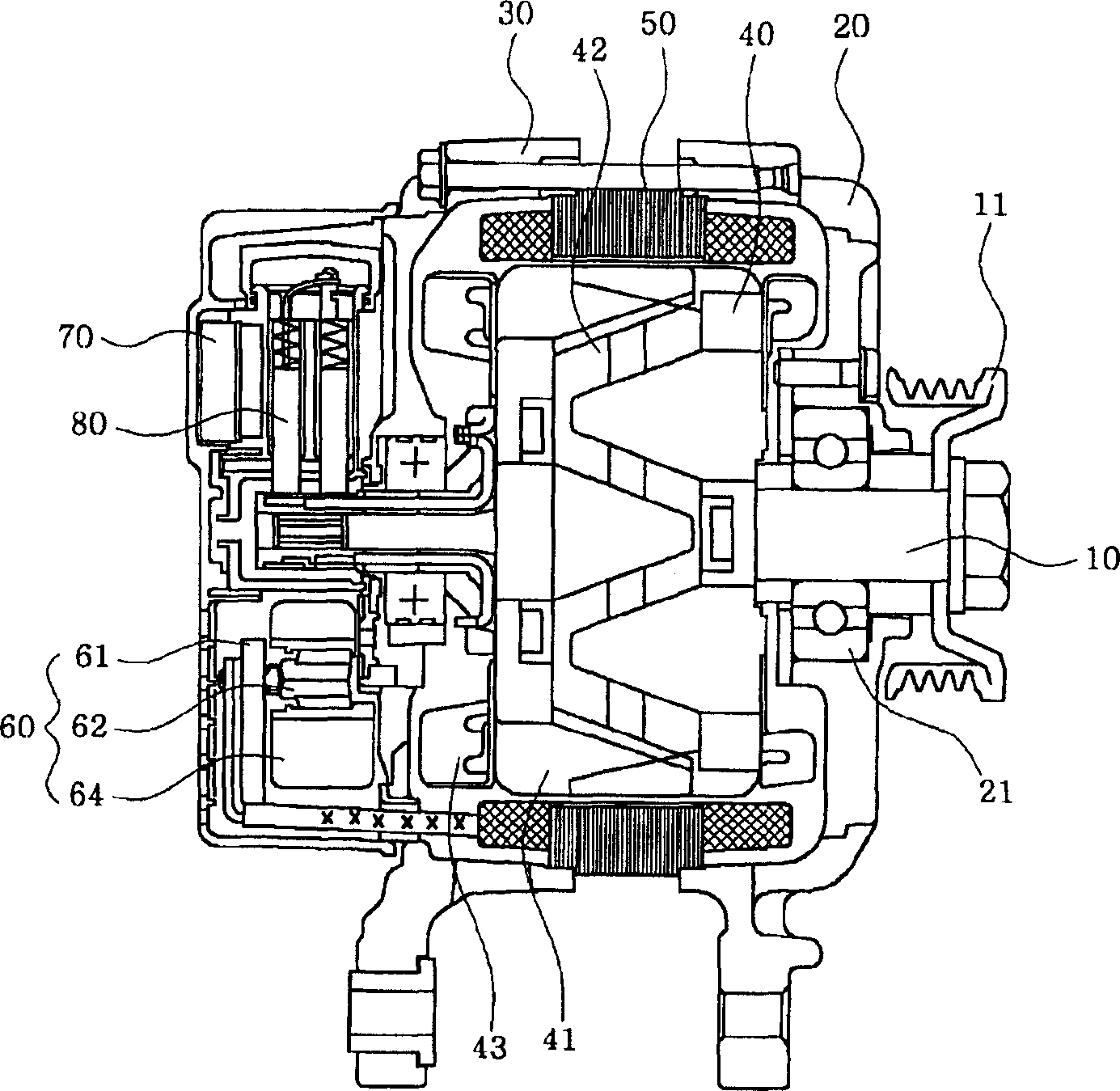
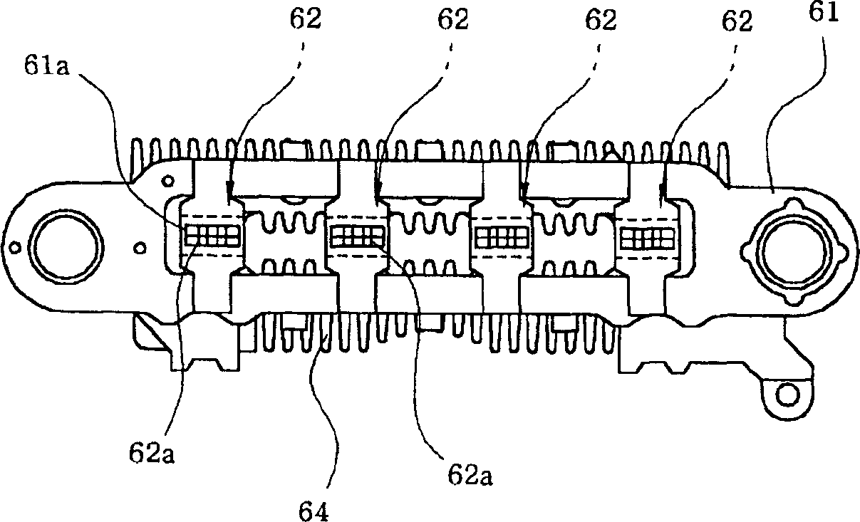
[0022] Figure 4 To show a side view of an alternator according to an embodiment of the present invention, Figure 5 It is a structural diagram of the rectifying device of the present invention.

[0023] First of all, the alternator using the rectifying device 60 of the present invention is also compatible with figure 1 As shown, the rotating shaft 10 supported by the respective bearings 21 at the center of the front bracket 20 and the rear bracket 30 in the state fixed to the end thereof by the pulley 11 is installed in the middle section of the rotating shaft and includes a magnetic field core 41 and the rotor device 40 with the coil 42 wound inside it, and the stator 50 surrounding the rotor device in a state fixed between the front bracket 20 and the rear bracket 30, and in the rear bracket The rectifying device 60 , the voltage regulator 70 and the brush suppor...


PUM


Abstract

The invention relates to the commutating device of the alternating current generator used in the vehicles. The invention aims to the following aspects: arrange the diodes around the cooling fan in equidistance to maximize the cooling effect; on the other hand, make the subsidy diodes come out of the terminal plate to increase the cooling effect of the subsidy diodes. The commutating device (60) is composed of the terminal plate (61), thermal fins (64) fixed on one surface of the abovementioned terminal plate (61), multiple diodes (62), which lies between the thermal fins and whose terminal (62a) stand out of the terminal hole (61a) of the abovementioned terminal plate (61), and the subsidy diodes crossing the abovementioned terminal plate (61) along it width. Arrange the multiple diodes (62) around the cooling fan (43) possessed by the stator device (40) in equidistance.

Description

technical field [0001] The present invention relates to a rectifier device for an automotive alternator, and more specifically, it is characterized by improving the position of rectifier diodes and the structure of a terminal board for arranging these diodes in the rectifier device so as to improve the rectification function. Background technique [0002] Typically, automotive alternators such as figure 1 As shown, the rotating shaft 10 supported by the respective bearings 21 at the center of the front bracket 20 and the rear bracket 30 in the state where the pulley 11 is fixed at its end is installed in the middle section of the rotating shaft and includes a magnetic field core 41 and the rotor device 40 with the coil 42 wound therein, the stator 50 surrounding the rotor device in a state fixed between the front bracket 20 and the rear bracket 30, and the stator 50 provided on the rear bracket 30 inside the rectifier device 60, voltage regulator 70 and brush support device...

Claims


Application Information

Patent Timeline
Patent Type & Authority Applications(China)
IPC IPC(8): H02K9/00H02K9/06H02K11/04
Inventor 黄三東朴顺植
Owner VALEO ELECTRICAL SYST KOREA
Why Eureka
Try Eureka