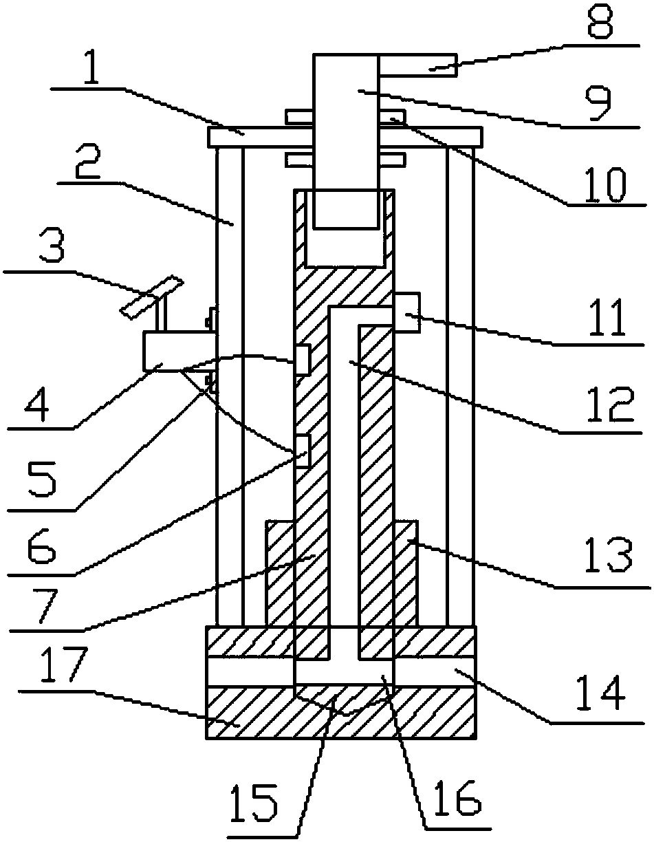
Self-heating control valve

A control valve, self-heating technology, applied in the valve heating/cooling device, valve details, valve device and other directions, can solve the problems of limited effect, the valve core of the drain valve can not work normally, the drain valve can not be used, etc., to achieve practical Strong, prevent water from freezing, easy to make effects

Pending Publication Date: 2018-07-20
TIANJIN ZHI YUAN IND & TRADE
View PDF0 Cites 0 Cited by
  • Summary
  • Abstract
  • Description
  • Claims
  • Application Information

AI Technical Summary

Problems solved by technology

[0002] Existing drain valves cannot be used in low-temperature environments. When the temperature is lower than 0°C, the water in the drain valve will freeze, making the spool in the drain valve unable to work normally.
Insulation cotton or pipe fittings of insulation material are usually used, but the effect is limited

Method used


Image

  • Self-heating control valve

Examples


Embodiment Construction

[0017] It should be noted that, in the case of no conflict, the embodiments of the present invention and the features in the embodiments can be combined with each other.

[0018] In describing the present invention, it should be understood that the terms "center", "longitudinal", "transverse", "upper", "lower", "front", "rear", "left", "right", " The orientations or positional relationships indicated by "vertical", "horizontal", "top", "bottom", "inner" and "outer" are based on the orientations or positional relationships shown in the drawings, and are only for the convenience of describing the present invention and Simplified descriptions, rather than indicating or implying that the device or element referred to must have a particular orientation, be constructed and operate in a particular orientation, and thus should not be construed as limiting the invention. In addition, the terms "first", "second", etc. are used for descriptive purposes only, and should not be understood ...


PUM


Abstract

The invention provides a self-heating control valve. A rotating mechanism is connected to the top end of a valve needle in a threaded mode, and a plurality of heating plates can be connected to the outer wall of the valve needle in an inserted mode. The self-heating control valve has the advantages that solar energy is used for heating the valve needle to prevent internal water from freezing in winter, the heating plate adopts an inserting-connecting mode, and the operation is simple.

Description

technical field [0001] The invention belongs to the field of control valves, in particular to a self-heating control valve. Background technique [0002] The existing drain valve cannot be used in a low-temperature environment. When the temperature is lower than 0°C, the water in the drain valve will freeze, so that the valve core in the drain valve cannot work normally. Insulation cotton or pipe fittings of insulation material are usually used, but the effect is limited. Contents of the invention [0003] In view of this, the present invention aims to propose a self-heating control valve, which can solve the above technical problems. [0004] In order to achieve the above object, technical solution of the present invention is achieved in that way: [0005] A self-heating control valve, including a bracket, a valve seat and a valve needle that cooperate with each other. The valve needle is provided with a water passage, and the position near the bottom of the valve needl...

Claims


Application Information

Patent Timeline
IPC IPC(8): F16K49/00
CPCF16K49/002
Inventor 孟繁君庞东生
Owner TIANJIN ZHI YUAN IND & TRADE
Why Eureka
Try Eureka