Wind speed measurement instrument, wind speed measurement method and device and storage medium
An anemometer and wind speed measurement technology, which is applied in the direction of measuring device, fluid speed measurement, speed/acceleration/impact measurement, etc., can solve the problem of being easily affected by external temperature and pressure, poor measurement stability, and the difficulty of thermal induction wind speed measurement methods. Affected by external temperature and other issues
- Summary
- Abstract
- Description
- Claims
- Application Information
AI Technical Summary
Problems solved by technology
Method used
Image
Examples
Embodiment 1
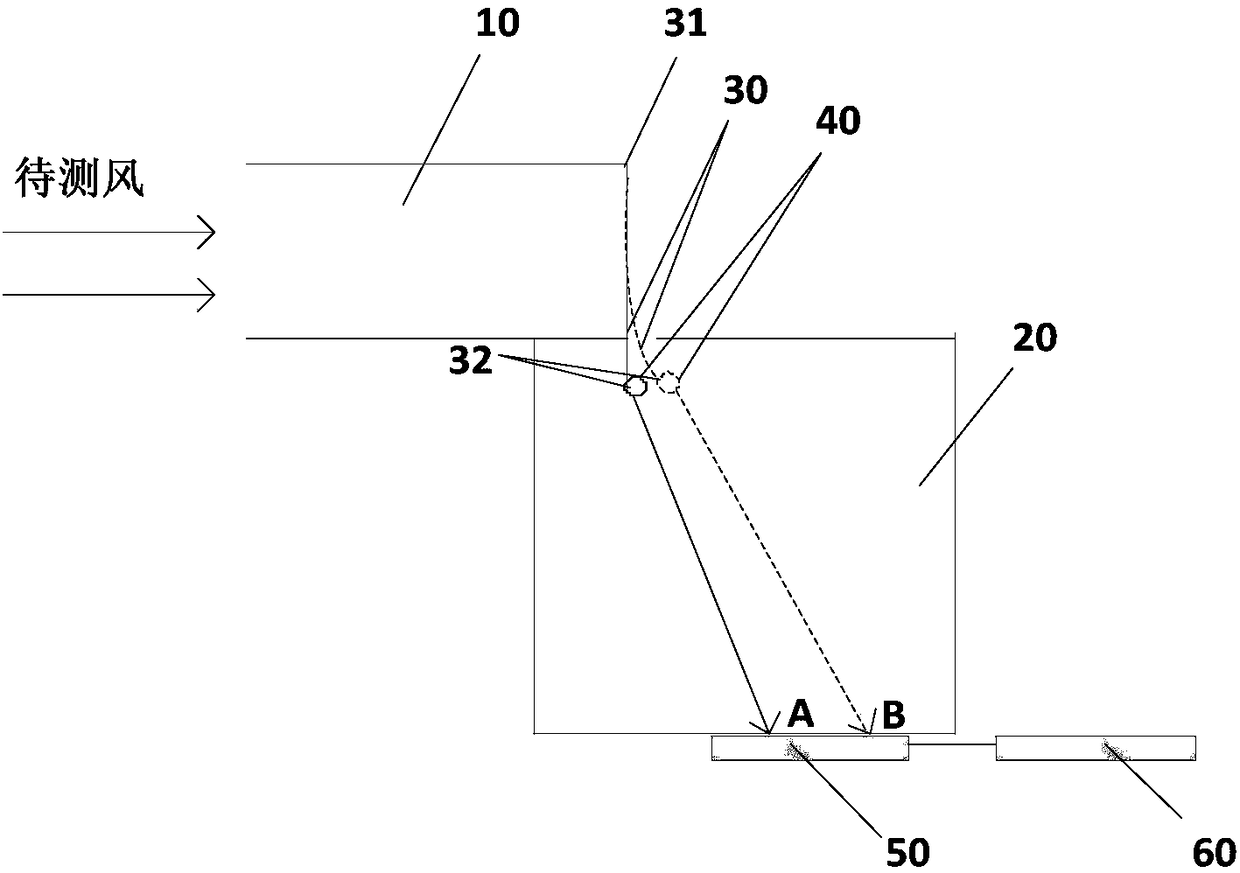
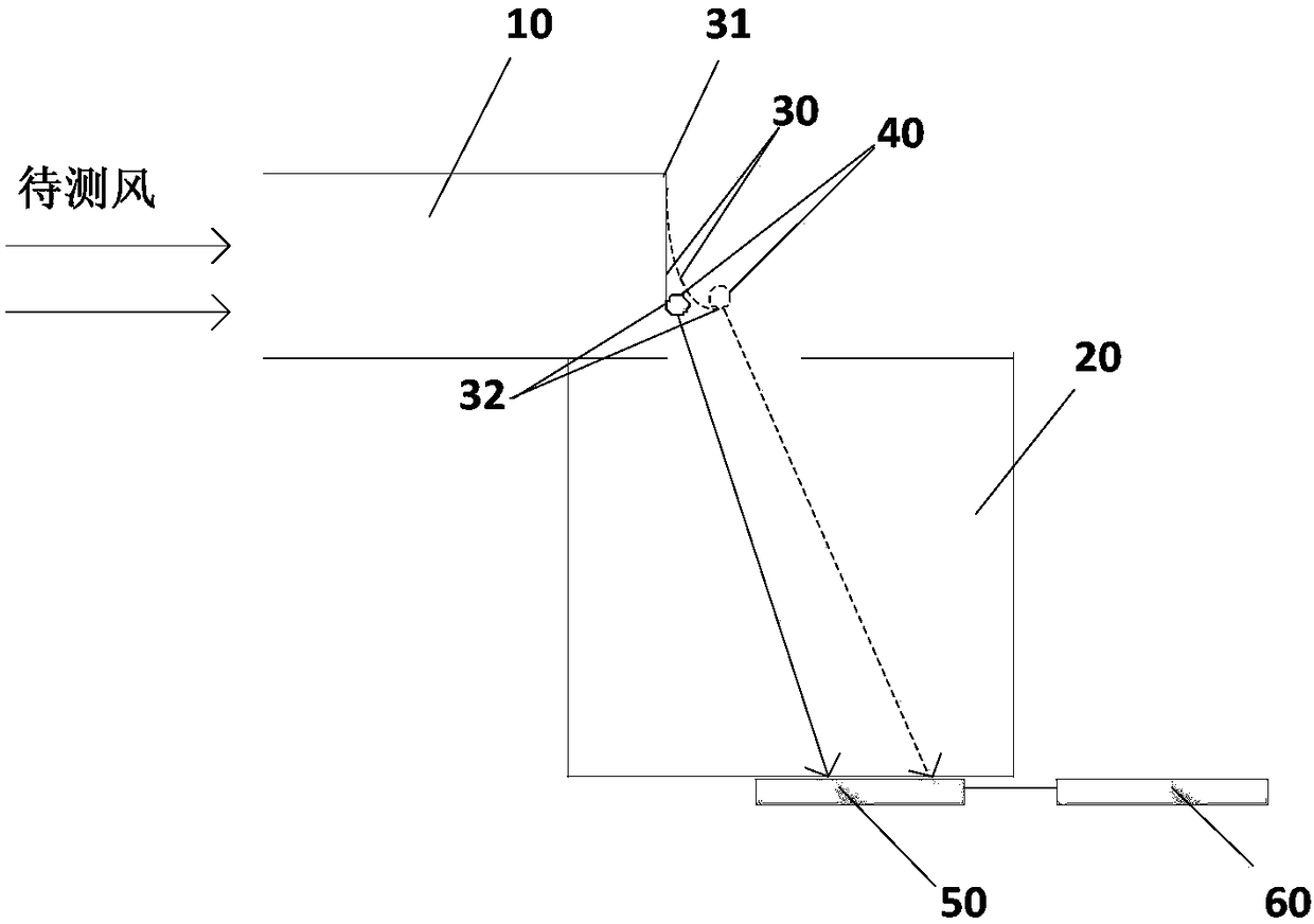
[0030] Figure 1a It is a schematic structural diagram of an anemometer provided in Embodiment 1 of the present invention. like Figure 1a As shown, the anemometer includes: a measurement cavity air inlet channel 10 , a measurement cavity optical path channel 20 , an elastic baffle 30 , a light source 40 , an optical detector 50 and a processor 60 .
[0031] Wherein, one end of the air inlet channel 10 of the measurement chamber is open, providing an inlet channel for the wind to be measured. The cross-sectional shape of the air inlet channel 10 of the measurement chamber can be rectangular, circular, elliptical, rhombus, trapezoidal, etc., and the present invention does not limit the cross-sectional shape.
[0032] Measuring cavity air inlet channel 10 communicates with measuring cavity optical path channel 20. Optionally, the cross-sectional shape of measuring cavity optical path channel 20 may be the same as or different from the cross-sectional shape of measuring cavity ai...
Embodiment 2
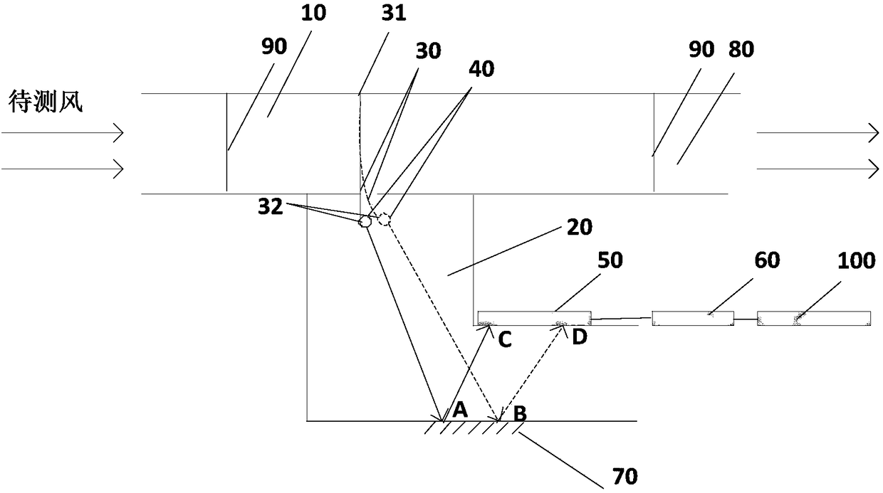
[0043] Figure 2a It is a schematic structural diagram of an anemometer provided in Embodiment 2 of the present invention. like Figure 2aAs shown, the anemometer also includes at least one mirror 70 fixed in the optical path channel 20 of the measuring cavity. Optionally, at least one mirror 70 is fixed on the wall of the optical path channel 20 of the measurement cavity. Among them, the mirror is a plane mirror; according to the degree of reflection, the mirror can be divided into a total reflection mirror and a half reflection mirror (also known as a beam splitter).
[0044] The number of reflecting mirrors 70 may be one, two or more than two. When there is one reflector 70 , the reflector 70 is used to directly reflect the light to the optical detector 50 . When there are two or more reflectors 70 , the reflectors 70 are arranged at intervals on opposite surfaces of the optical path channel 20 of the measuring cavity, and are used to continuously reflect light to the o...
Embodiment 3
[0058] image 3 It is a flow chart of the method for measuring wind speed provided by Embodiment 3 of the present invention. This embodiment is applicable to the situation of measuring wind speed, especially the case of relatively small wind speed. The method can be performed by an wind speed measuring device, and specifically includes the following steps:
[0059] S110. Obtain the projection position of the light emitted by the light source on the optical detector, wherein, under the wind force of the wind to be measured, the direction of the light emitted by the light source changes.
[0060] Optionally, the optical detector is a psd position sensor, which is used to detect the projection position of the light on the optical detector 50 .
[0061] Under the wind force of the wind to be measured, the light emitting direction of the light source changes. The light emitting direction points to the optical detector, and the projection position of the light detected by the opti...
PUM
 Abstract
Description
Claims
Application Information
 - R&D
- Intellectual Property
- Life Sciences
- Materials
- Tech Scout
- Unparalleled Data Quality
- Higher Quality Content
- 60% Fewer Hallucinations
Browse by: Latest US Patents, China's latest patents, Technical Efficacy Thesaurus, Application Domain, Technology Topic, Popular Technical Reports.
© 2025 PatSnap. All rights reserved.Legal|Privacy policy|Modern Slavery Act Transparency Statement|Sitemap|About US| Contact US: help@patsnap.com


