Method for predicting turning machining deformation of thin-wall complex curved surface rotating member

A complex surface, processing deformation technology, applied in special data processing applications, instruments, electrical and digital data processing and other directions, can solve problems such as affecting accuracy, non-uniform distribution, etc., to achieve moderate calculation, general requirements, both efficiency and accuracy. sexual effect

Active Publication Date: 2018-07-20
DALIAN UNIV OF TECH
View PDF2 Cites 6 Cited by
  • Summary
  • Abstract
  • Description
  • Claims
  • Application Information

AI Technical Summary

Problems solved by technology

However, for the machining of complex curved surface rotary parts, due to its shape characteristics, even under the condition of constant speed, cutting depth and feed rate, the feed direction is constantly changing during the machining process, and the tool is constantly moving along the x-axis of the machine tool, resulting in actual The main declination angle and the cutting line speed are also constantly changing, which directly leads to the non-uniform distribution of residual stress at different processing parts along the z-axis of the machine tool
Therefore, when predicting the machining deformation of thin-walled and complex curved parts, it is relatively simple to apply a uniform residual stress field, but it obviously affects the accuracy of the prediction because it does not match the actual situation.
So far, for thin-walled complex curved parts, the machining deformation prediction method considering the non-uniformity of residual stress distribution has not appeared in the relevant literature and patents

Method used


Image

  • Method for predicting turning machining deformation of thin-wall complex curved surface rotating member
  • Method for predicting turning machining deformation of thin-wall complex curved surface rotating member
  • Method for predicting turning machining deformation of thin-wall complex curved surface rotating member

Examples


Embodiment Construction

[0046] The specific implementation manners of the present invention will be further described below in conjunction with the accompanying drawings and technical solutions.

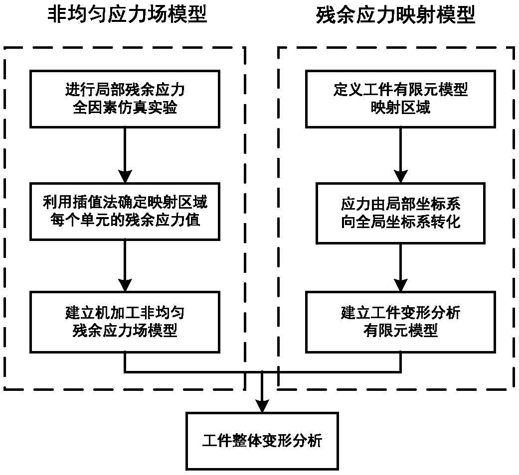
[0047] The flow chart of a method for predicting turning deformation of thin-walled rotary parts is as follows figure 1 As shown, the specific implementation process of the present invention will now be described in detail with reference to the accompanying drawings and specific embodiments. It should be noted that the specific embodiments described here are only used to explain the present invention, not to limit the present invention.

[0048] (a) Carry out 2-factor multi-level full factorial test to obtain the residual stress distribution under each combination: according to the given three cutting elements and the shape of the workpiece, determine the two factors of the main deflection angle and the cutting line speed in the actual machining process Variation range; when taking the value of the main de...


PUM


Abstract

The invention relates to a method for predicting turning machining deformation of a thin-wall complex curved surface rotating member, and belongs to the technical field of machining. Firstly, a tool cutting edge angle and cutting line speed are taken as experimental factors, a two-factor multi-level full factor test is performed to obtain residual stress distribution under each kind of combination; then, according to the obtained multiple sets of residual stress distribution, local residual stress values corresponding to different places in a surface stress layer are obtained by a multidimensional linear interpolation method, and the reconstruction of the machining of a non-even residual stress field is completed; then, according to a position relationship of a local coordinate system anda global coordinate system, the conversion from a local stress field to a global stress field is achieved; lastly, loads and boundary conditions are applied, and the rotating member turning machiningdeformation on the thin-wall complex curved surface is calculated. According to the method for predicting the turning machining deformation of the thin-wall complex curved surface rotating member, thenon-uniformity of processing residual stress distribution caused by related parameter changes in the actual processing of the thin-wall complex curved surface rotating member is considered, thereby the calculation amount of the method is moderate, the quality requirement for grids is general, and the efficiency and the accuracy are simultaneously achieved.

Description

technical field [0001] The invention relates to a method for predicting the turning deformation of a thin-walled complex curved surface rotary part, which belongs to the technical field of mechanical processing. Background technique [0002] With the development of my country's aerospace, energy and power industries, the use of thin-walled parts is increasing, and its precision requirements are also getting higher and higher. However, due to its weak rigidity, the thin-walled parts are easily deformed during the machining process, which eventually leads to out-of-tolerance and cannot be used. The main factors affecting the deformation of thin-walled parts are cutting force, clamping, initial residual stress and machining residual stress. For thin-walled parts, machining residual stress contributes more to its deformation. At present, relevant scholars have carried out a lot of research work on the prediction of machining deformation of thin-walled parts, mainly focusing on...

Claims


Application Information

Patent Timeline
Patent Type & Authority Applications(China)
IPC IPC(8): G06F17/50
CPCG06F30/17
Inventor 孙玉文王昊段春争徐金亭
Owner DALIAN UNIV OF TECH
Why Eureka
Try Eureka