Automatic locating device

A technology of automatic positioning and limit plate, applied in the direction of transportation and packaging, conveyor objects, etc., can solve the problems of low degree of automation and poor connection, and achieve the effect of high degree of automation and good motion accuracy

Inactive Publication Date: 2018-07-24
昆山木利机械设计有限公司
View PDF0 Cites 4 Cited by
  • Summary
  • Abstract
  • Description
  • Claims
  • Application Information

AI Technical Summary

Problems solved by technology

[0004] (1) The two groups of mechanisms move together, and their connection is poor;
[0005] (2) Manually driven to do horizontal movement, the degree of automation is low

Method used


Image

  • Automatic locating device

Examples


Embodiment Construction

[0030] Specific embodiments of the present invention will be further described in detail below.

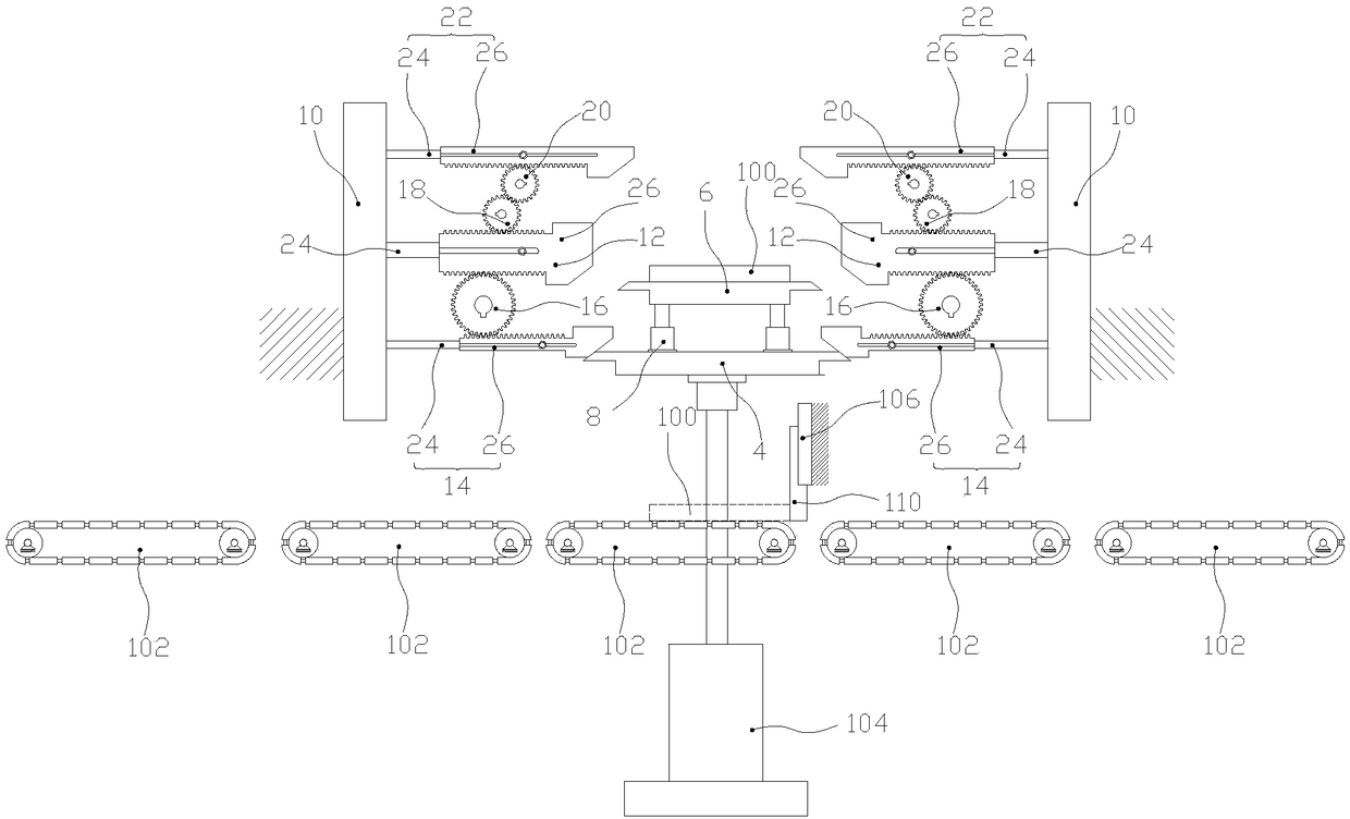
[0031] Such as figure 1 As shown, the present invention includes

[0032] A horizontal conveying mechanism 102 for transporting the workpiece 100 in the horizontal direction;

[0033] The lifting mechanism 104 located on the movement stroke of the horizontal conveying mechanism 102, the lifting mechanism 104 is used for receiving or placing the workpiece 100 on the horizontal conveying mechanism 102 from bottom to top;

[0034] The limit baffle 106 on the horizontal conveying mechanism 102 is used to contact the horizontal worktable 6 on the horizontal conveying mechanism 102 and stop it from moving. The workpiece 100 is moved by the lifting mechanism 104 Undertake the lifting movement, and the position when it stops ensures the positioning of the workpiece 100 on the lifting mechanism 104;

[0035] Located directly above the lifting mechanism 104 and symmetrically arranged alo...


PUM


Abstract

The invention discloses an automatic locating device. The automatic locating device is characterized in that the automatic locating device comprises horizontal conveying mechanisms, an elevating mechanism, a limiting baffle and two limiting plates. According to the automatic locating device, firstly, a workpiece performs horizontal motion under the effect of the horizontal conveying mechanisms; when moving onto a horizontal workbench, the workpiece is in contact with the limiting baffle; the elevating mechanism drives the horizontal workbench to ascend, and the elevating height of the horizontal workbench is higher than a set standard position; after the horizontal workbench ascends and goes over the limiting plates, the limiting plates perform relative motion, so that the clearance between the limiting plates is smaller than the horizontal size of the horizontal workbench; and after ascending to a travel top point, the horizontal workbench is driven to descend and put onto the limiting plates, and at the moment, the position of the horizontal workbench is the standard position. By means of the automatic locating device, problems found in the prior art are well solved; linkage between the horizontal motion and the ascending-and-descending motion is guaranteed; and the automatic locating device is high in automation degree and good in motion precision.

Description

technical field [0001] The invention relates to an automatic positioning device. Background technique [0002] When the workpiece moves from position A to position B on the slant, it usually moves horizontally to the corresponding position first, and then lifts it vertically to the set position. [0003] The above-mentioned movement is usually completed by two groups of mechanisms, or the movement on the horizontal position is completed manually, and then lifted to the set position by the machine. Therefore inevitably there are the following problems: [0004] (1) The two groups of mechanisms move together, and their connection is poor; [0005] (2) It is manually driven to do horizontal movement, and its degree of automation is low. Contents of the invention [0006] The purpose of the present invention is to provide a high degree of automation, and a plurality of mechanisms interlocking movement device. [0007] In order to solve the above problems, the present inven...

Claims


Application Information

Patent Timeline
Patent Type & Authority Applications(China)
IPC IPC(8): B65G47/22B65G47/34
CPCB65G47/22B65G47/34
Inventor 王芒利
Owner 昆山木利机械设计有限公司
Why Eureka
Try Eureka