
Self-rope-arranging winch

A hoist and self-draining rope technology, which is applied to hoisting devices and clockwork mechanisms, can solve problems such as no direction of the rope, and achieve the effects of stable pulley movement, orderly placement, and ease of use

Pending Publication Date: 2018-07-24
江苏中惠舞台设备技术有限公司
View PDF1 Cites 13 Cited by
  • Summary
  • Abstract
  • Description
  • Claims
  • Application Information

AI Technical Summary

Problems solved by technology

[0004] In the above technical solution, due to the use of the screw nut drive, the reel can realize the left and right reciprocating movement during the rotation process, but because there is no fixed direction of the rope, in the actual use process, the wire rope is strung together, and the wire rope is retracted. The phenomenon of process superposition is still very obvious

Method used


Image

  • Self-rope-arranging winch
  • Self-rope-arranging winch
  • Self-rope-arranging winch

Examples


Embodiment Construction

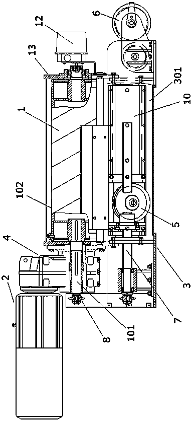
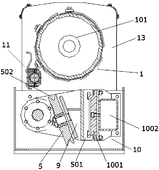
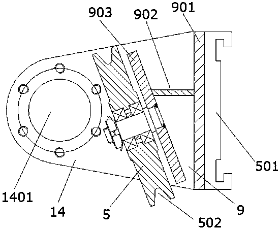
[0028] Such as figure 1 Shown is the self-draining rope winch of the present invention, including a reel 1, a motor 2 and a base 3, the motor 2 is connected with a speed reducer 4, and the reel 1 is installed on the base 3; The machine 4 is connected with the reel shaft 101 of the reel 1 to drive the reel 1 to rotate; there is a pulley 5 under the reel 1, and the pulley 5 moves along the axial direction of the reel 1; The radial section of the pulley 5 is perpendicular to the radial section of the reel 1, and forms an included angle of 21 degrees with the axial section of the reel 1 (it can also be any angle between 10-40), such as figure 2 As shown; also includes a rope guide wheel 6, the rope guide wheel 6 is arranged on the base 3, and the wire rope is discharged from the reel 1 and is discharged by the rope guide wheel 6 after winding around the pulley 5 ; Both ends of the reel 1 have a vertical plate 13, and the end of the reel shaft 101 is flush with the outer surface ...


PUM


Abstract

The invention discloses a self-rope-arranging winch. The self-rope-arranging winch comprises a winding drum, a motor and a base. The motor is connected with a speed reducer, and the winding drum is installed on the base. The speed reducer is connected with a winding drum shaft of the winding drum to drive the winding drum to rotate. The self-rope-arranging winch further comprises pulleys. The pulleys move in the axial direction of the winding drum and further comprises a rope guide wheel. Steel wire ropes are unwound from the winding drum and are arranged by the rope guide wheel after bypassing the pulleys. By arranging the pulleys and the rope guide wheel, the horizontal installation, ceiling installation and vertical installation of the self-rope-arranging winch can be realized on the basis of the fixed and unified rope output direction without affecting the rope output direction, the use is convenient, the steel wire ropes can be orderly wound around the winding drum, and the synchronous lifting of all lifting points can be ensured.

Description

technical field [0001] The invention belongs to the technical field of stage equipment, and in particular relates to a self-draining rope winch for fixing the direction of the rope out. Background technique [0002] The horizontal boom can be used in studios, movie studios and theaters to hang lamps and lanterns. It mainly uses an electric transmission mechanism to drive the horizontal boom with lamps to rise, fall or move in parallel. In the prior art, during operation, the reel of the boom machine only performs rotational movement, but does not perform horizontal displacement, so it is easy to produce the phenomenon of overlapping and stringing of wire ropes, which in turn leads to danger; moreover, due to the existing The defect of the transmission structure of the horizontal boom leads to large shaking of the horizontal boom when it performs the rotating function and horizontal walking, which directly affects the lighting effect. [0003] In the Chinese patent document ...

Claims


Application Information

Patent Timeline
IPC IPC(8): B66D1/39
CPCB66D1/39
Inventor 孙拂晓
Owner 江苏中惠舞台设备技术有限公司
Learn More