Ball catch locking device

A bead door buckle and bead-touching technology, which is used in door/window fittings, rod connections, folding panels, etc.

Active Publication Date: 2018-07-24
OTTO GANTER GMBH & CO KG NORMTEILEFAB
View PDF8 Cites 5 Cited by
  • Summary
  • Abstract
  • Description
  • Claims
  • Application Information

AI Technical Summary

Problems solved by technology

[0008] The flippers known from the prior art have the disadvantage that the adjusting screws of the individual compression springs are always visible from the outside

Method used


Image

  • Ball catch locking device
  • Ball catch locking device
  • Ball catch locking device

Examples


Embodiment Construction

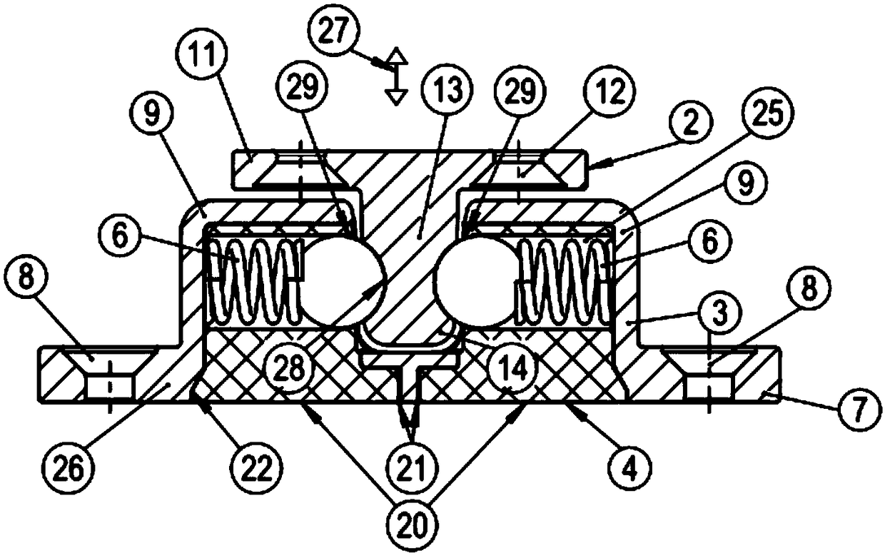
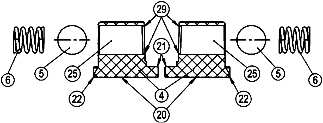
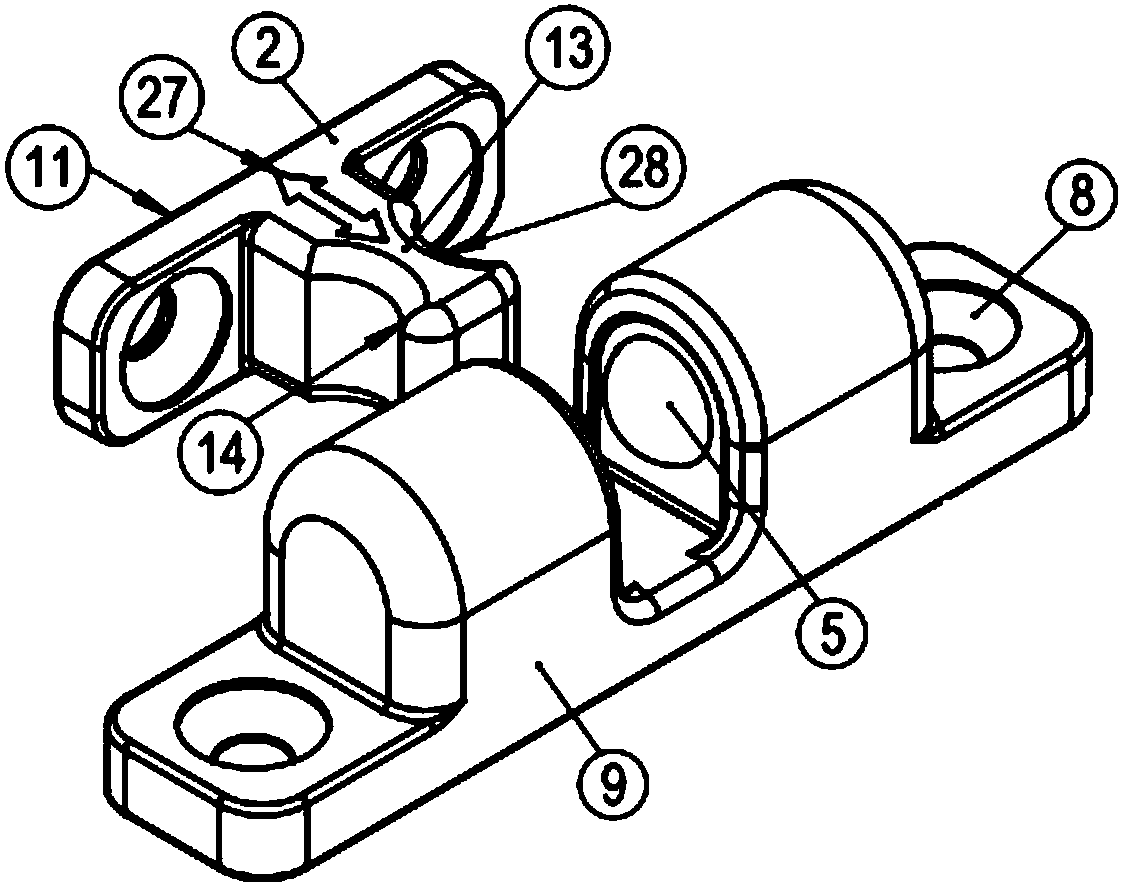
[0043] according to figure 1 and 11 , the tumbler 1 of the invention is characterized by a centering element 2 consisting of a mounting plate 11 on which the pin 13 is molded. The pin 13 has a thickening 14 at the end facing away from the mounting plate 11 . This thickening makes it possible to engage the bead 5 in the recess 28 behind the thickening 14 .

[0044] Furthermore, the centering element 2 has a hole 12 on its mounting plate 11 for fastening the centering element 12 at a mounting surface not shown. The centering element 2 is inserted into the latch housing 26 in the direction of the arrow 27 .

[0045] The catch housing 26 is formed from two opposing bushings 9 , which correspondingly have opposing windows 17 . Furthermore, the latch housing 26 has a mounting plate 7 molded on the bushing or on the housing wall 3 , which has a hole 8 . The holes 8 are used to fit the catch housing 26 on a mounting surface not shown.

[0046]Located in the bushing 9 is the bead...


PUM


Abstract

A ball catch (1) having a catch housing (26) with two spring-loaded balls (5) which are displaceable therein under spring loading, and which are supported in two oppositely situated sockets (9) of thecatch housing (26) and protrude in a diametrically opposed manner into a middle receiving space (10) between the sockets (9), and a centering part (2) which with a journal (13) integrally formed thereon is insertable into the receiving space (10) and is lockable by the balls (5) at that location, wherein the ball guide (4) for the balls (5) and the compression springs (6) is inserted into the catch housing (26) as a separate part.

Description

technical field [0001] The object of the invention is a tumbler according to the preamble of patent claim 1 . Background technique [0002] A tumbler lock acts as a locking device for two mutually movable components and is known, for example, in DE 199 11 275 A1. The tumbler latch indicated here consists of a locking part with a bolt molded into it and a striker housing, wherein the striker housing surrounds the engagement pin and thus locks the two components to one another. [0003] The component accordingly has a rectangular, slightly elongated mounting plate, on the end sections of which are formed passage holes for fastening screws. [0004] These holes are used for fastening the individual components to, for example, the fastening plane of the door and the body of the cabinet. The catch housing consists of two spaced and aligned bushings molded onto the mounting plate. The area between the bushings serves as a receiving chamber, into which the pins of the centering ...

Claims


Application Information

Patent Timeline
Patent Type & Authority Applications(China)
IPC IPC(8): E05C19/04
CPCE05C19/04E05B63/0056E05D5/02F16B2/16F16B7/042
Inventor 亚历山大·皮彻丁
Owner OTTO GANTER GMBH & CO KG NORMTEILEFAB
Why Eureka
Try Eureka