bead door buckle

A technology of bead door buckle and bead touching, which is applied in door/window fittings, rod connection, folding board, etc., to achieve the effect of low-cost production

Active Publication Date: 2020-08-04
OTTO GANTER GMBH & CO KG NORMTEILEFAB
View PDF8 Cites 0 Cited by
  • Summary
  • Abstract
  • Description
  • Claims
  • Application Information

AI Technical Summary

Problems solved by technology

[0008] The flippers known from the prior art have the disadvantage that the adjusting screws of the individual compression springs are always visible from the outside

Method used


Image

  • bead door buckle
  • bead door buckle
  • bead door buckle

Examples


Embodiment Construction

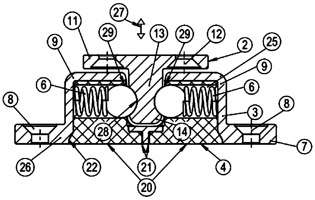
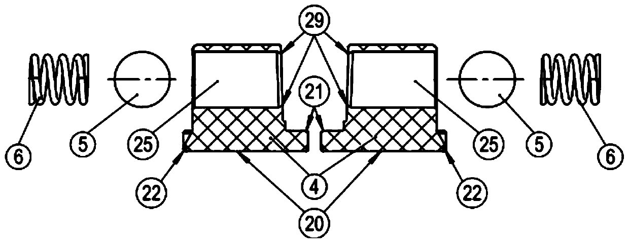
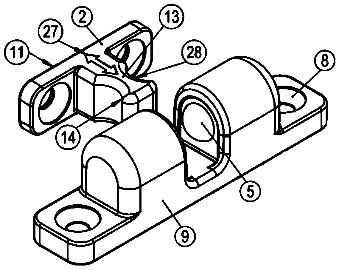
[0043] according to figure 1 with 11 The feature of the ball bumper door buckle 1 of the present invention is that the centering member 2 is composed of an assembly plate 11, and the pin 13 is molded at the assembly plate. The pin 13 has a thickened portion 14 at the end facing away from the assembly plate 11. This thickened portion makes it possible to engage the bumper 5 in the recess 28 coupled behind the thickened portion 14.

[0044] In addition, the centering member 2 has a hole 12 at its mounting plate 11 for fixing the centering member 12 to a mounting surface not shown. The centering piece 2 is inserted into the buckle housing 26 in the arrow direction 27.

[0045] The buckle housing 26 is composed of two opposite bushings 9, which correspondingly have opposite windows 17. In addition, the buckle housing 26 has a mounting plate 7 molded at the bushing or housing wall 3 with holes 8. The hole 8 is used to assemble the door buckle housing 26 on an assembly surface not sho...


PUM


Abstract

Knock-ball latch (1) with latch housing (26), with at least two snap-bolts (5) spring-loaded and movably supported therein, which are supported on the latch housing (26 ) of the two opposite bushings (9) and reversely and identically project into the intermediate housing chamber (10) between the bushings (9), and with a centering piece (2), which The pin (13) formed thereon is inserted into the receiving cavity (10) and can be locked there by the bead (5), wherein the bead guide (4) for the bead (5) and The compression spring (6) is installed in the latch housing (26) as a separate part.

Description

Technical field [0001] The object of the present invention is a ball bumper. Background technique [0002] The ball latch serves as a locking device for two mutually movable members and is disclosed, for example, in DE 199 11 275 A1. The ball bumper mentioned here is composed of a locking member with a pin molded thereon and a buckle housing, wherein the buckle housing surrounds the embedding pin and thus locks the two components to each other. [0003] The component correspondingly has a rectangular, slightly elongated mounting plate, which is formed with through holes for fixing screws at its end sections. [0004] These holes are used to fix various components on, for example, the fixing plane of the door and the cabinet body of the cabinet. The buckle housing consists of two spaced and aligned bushings molded on the assembly plate. The area between the bushes serves as a receiving cavity in which the pin of the centering piece can be inserted and locked. [0005] There are bump...

Claims


Application Information

Patent Timeline
Patent Type & Authority Patents(China)
IPC IPC(8): E05C19/04
CPCE05C19/04E05D5/02F16B2/16E05B63/0056F16B7/042
Inventor 亚历山大·皮彻丁
Owner OTTO GANTER GMBH & CO KG NORMTEILEFAB
Why Eureka
Try Eureka